What will be the role of a copper layer in a metal core PCB in thermal dissipation?

In the design of a power electronic PCB, I want to use a metal PCB for heat dissipation of a TO-220 package MOSFET. To do that I want to mount metal PCB on the MOSFET with the use of thermal paste and screw exactly like we do when we use heatsink for the same package. Should I leave the copper of PCB between MOSFET surface and dielectric of PCB or remove the copper surface and leave only the dielectric opening?

I doubt it makes much difference unless the copper extends beyond the contact that would exist with the dielectric.

If the copper extends, you’ll have better lateral heat spreading and that will conduct through the dielectric so there will be less temperature drop across the dielectric.

Copper conducts heat about 400x better than the dielectric (which may be 50-200um thick) and is typically 35 or 70um thick (1oz/2oz). So extending it at least a few mm should help a little. I’m not sure it’s a huge difference, even at 200um and 1.0 W/m*K the temperature drop at (say) 5W is less than 7°C if I did the sums correctly (10mm x 15mm contact). If a 15 x 20mm pad was isothermal (which it won’t be but say it was a bit bigger than that), then it would reduce the drop to half, saving a few °C. The savings would be proportionally less (or worse) if the dielectric was thinner, so it might not be much.

Devamını oku: Ağır Bakır PCB

#PCB Design #PCB Materials
Resmi Oliver Smith

Oliver Smith

Oliver, PCB tasarımı konusunda yetenekli deneyimli bir elektronik mühendisidir, analog devreler, gömülü sistemler, ve prototipleme. Derin bilgisi şematik yakalamaya kadar uzanıyor, cihaz yazılımı kodlaması, simülasyon, Yerleşim, test yapmak, ve sorun giderme. Oliver, elektrik tasarımı yeteneklerini ve mekanik yeteneğini kullanarak projeleri konsept aşamasından seri üretime geçirme konusunda uzmandır.

Başkaları Ne Soruyor?

PCB'deki kurşunsuz lehim bağlantılarındaki siyah noktalar nelerdir??

Bir PCB prototipi yapıyorum, Chip Quik'i kullanarak “SMDSWLF.031, Sn96.5/ Ag3.0/ Cu0.5 lehim 2.2% temiz olmayan akı. I find that the black spots appears frequently in larger pads on my board. I wonder if it is because I left the soldering iron more time heating the solder and that burnt the flux. What is that black residue? Is that a sign of a bad joint or maybe bad soldering technique?

Blog Makalelerinden Ayrıntılı Tavsiyeleri Okuyun

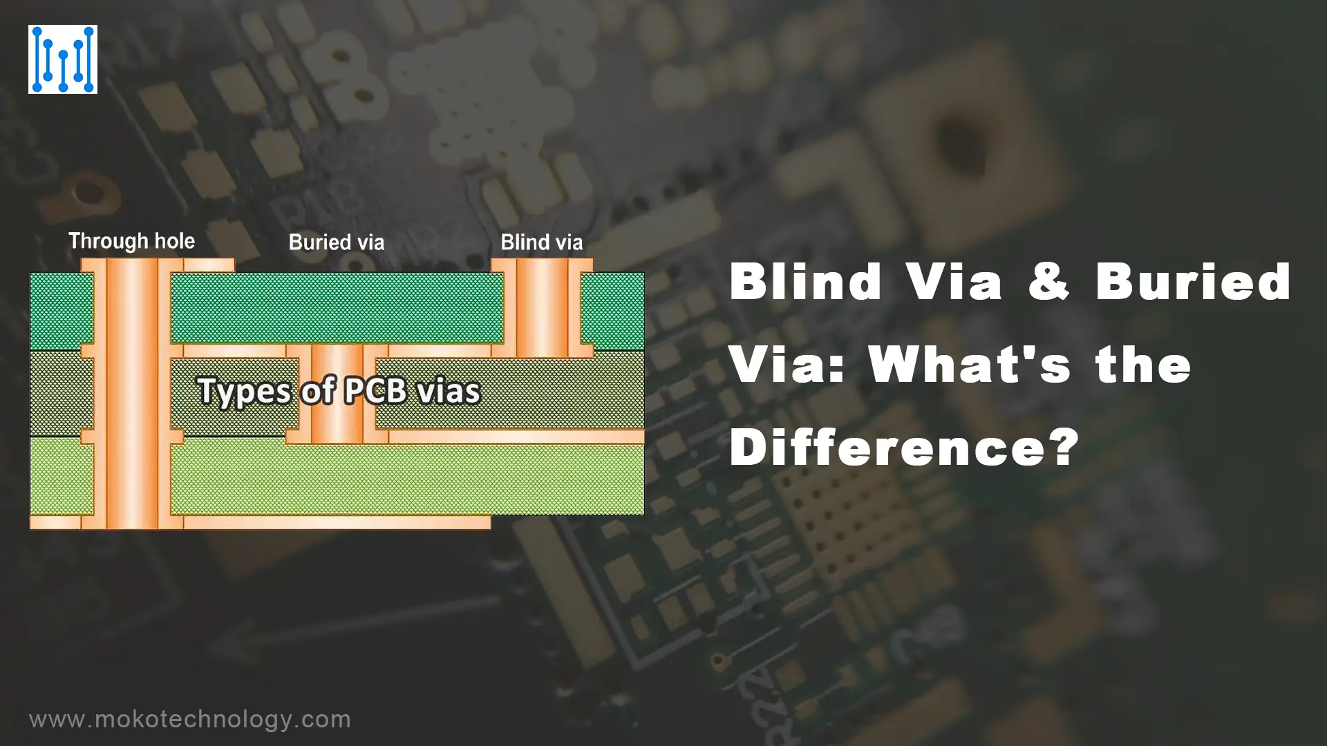
Kör Via & Gömülü Via: Fark ne?
ryan chan

Kör Via & Gömülü Via: Fark ne?

Teknolojideki gelişmeler PCB tasarımının sınırlarını zorlamaya devam ediyor, daha küçük ve daha karmaşık düzenler talep ediyor. İçinde karmaşık bağlantılar oluşturmaya gelince

Etkili Bluetooth Devre Kartları Nasıl Tasarlanır
ryan chan

Etkili Bluetooth Devre Kartları Nasıl Tasarlanır?

Bluetooth bugünlerde her yerde! Akıllı telefonlarda bulabilirsiniz, kulaklıklar, hoparlörler – Kablosuz olarak bağlanan hemen hemen her cihaz muhtemelen Bluetooth kullanıyor. Yani

Yukarı Kaydır