What are the black spots in lead-free solder joints on PCB?

I am prototyping a PCB, using Chip Quik's "SMDSWLF.031, a Sn96.5/ Ag3.0/ Cu0.5 solder with 2.2% no-clean flux. I find that the black spots appears frequently in larger pads on my board. I wonder if it is because I left the soldering iron more time heating the solder and that burnt the flux. What is that black residue? Is that a sign of a bad joint or maybe bad soldering technique?

Those dark splotches may be leftovers from the resin-based flux. No-clean fluxes are often made out of water-soluble resins (vs rosin) and during heating, most of it will evaporate away.

Pay attention to soldering temperatures. Sn96.5/Ag3.0/Cu0.5 solder’s liquidus is 217 ° C. Soldering at high temperatures you have been using can potentially damage components, has been weakening the glue under every pad you solder (the copper is glued to the FR4), producing significantly more hazardous fumes, something that is already more hazardous with lead-free solders, and generally does nothing good.

As far as I know, it should not have a meaningful impact on the joint, but if you want to avoid this, I suggest lowering your iron temperature (and possibly getting a new tip and/or iron depending, so soldering is effective at said lower temperature), though this may not totally resolve the issue.

consulte Mais informação: Protótipo de PCB

#Montagem de PCB #Projeto de PCB

Foto de OliverSmith

OliverSmith

Oliver é um engenheiro eletrônico experiente, especializado em design de PCB, circuitos analógicos, sistemas embarcados, e prototipagem. Seu profundo conhecimento abrange a captura esquemática, codificação de firmware, simulação, disposição, teste, e solução de problemas. Oliver se destaca em levar projetos desde o conceito até a produção em massa usando seus talentos de design elétrico e aptidão mecânica.

O que os outros estão perguntando

How do you usually organize SMT parts during PCB assembly?

Suppose one is hand-assembling a board with many SMT components. Unlike THT, SMT components are often not labeled. How might one keep small (<100) quantities of such parts properly organized during assembly? Are there particular tools? Storage devices? Methods?

Leia conselhos detalhados de artigos de blog

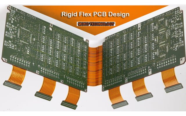
melhores práticas de rigid flex pcb
Ryan Chan

Melhores práticas de design de PCB Flex Rígido

Design Rigid Flex PCB: Benefícios e melhores práticas de design com o uso de uma PCI flexível rígida(FPC rígido), substratos de circuito flexíveis e substratos de circuito rígidos

Guia de Design de Empilhamento de PCB
Ryan Chan

Diretrizes de design de empilhamento de PCB

As pessoas esperam que os produtos eletrônicos sejam ricos em funções, mas também exigem que sejam pequenos e portáteis, que traz novos desafios para placa de circuito

Role para cima