The Ultimate Guide to FR4 PCB in 2025
FR4 PCB is one of the most widely used PCB types as it offers an excellent balance of performance, cost-effectiveness, and reliability. However, how much do you really know about this versatile material? In this comprehensive guide, we will introduce FR4 circuit boards from various aspects ensuring you have a thorough understanding of them.
What Does the FR4 Stand For?
FR4 is an abbreviation that stands for “Flame Retardant 4.” The “FR” part of the name indicates that the material is flame retardant, and the “4” in the name refers to the specific grade or classification of the flame-retardant material. FR4 is a material with a composite structure, which consists of an epoxy resin reinforced with woven glass cloth, providing both structural integrity and electrical insulation properties.
What Is FR4 PCB Board?
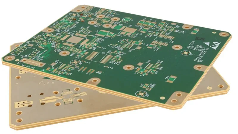
An FR4 PCB Board refers to a printed circuit board that is constructed using FR4 material. The manufacturing process begins with the use of FR4 as the insulating core layer of the circuit board. Subsequently, a layer of copper is applied to each side of the FR4 sheet, transforming it into what is known as copper-clad laminate (CCL). This combination of FR4 and copper layers ensures the PCB has the necessary insulation and conductivity for a wide range of electronic applications.
Properties of FR4 PCB Board
Flame Retardancy
As the name implies, FR4 boards are flame retardant. The addition of flame-retardant additives to the epoxy resin helps to prevent or slow down the spread of fire, enhancing safety in electronic devices.
Electrical Insulation
FR4 PCBs have excellent electrical insulation properties, thanks to the epoxy resin matrix. This ensures that the electrical signals traveling through the copper traces are isolated from each other, preventing short circuits and signal interference.
Mechanical Strength
The woven glass fiber reinforcement in FR4 circuit board provides strong mechanical strength and durability. This property ensures that the boards can withstand vibrations, impacts, and other physical stresses encountered in various applications.
Dielectric Properties
FR4 PCB boards have favorable dielectric properties, such as a relatively low dielectric constant and dissipation factor. These properties are important for high-frequency applications and signal integrity.
Heat Resistance
FR4 boards can withstand moderate temperatures without losing their integrity or experiencing significant deformation. This heat resistance is essential for applications where circuit board components generate heat while functioning.
The following is a chart that lists key parameters of FR4 printed circuit boards:
| Parameter | Typical Value |
|---|---|
| Dielectric Constant (at 1 MHz) | 4.0 – 4.7 |
| Dissipation Factor (at 1 MHz) | 0.017 |
| Water absorption | −0.125 in < 0.10% |
| Thermal Conductivity | 0.29 W/(M·K) through-plane |
| 0.81 W/(M·K) in plane | |
| Dielectric strength | 20 MV/m |
| Temperature Index | 140 °C (284 °F) |
| Temperature Index | > 120 °C |
Further reading: A Comprehensive Guide to FR4 Thermal Conductivity
Limitations of FR4 Circuit Board
• Insulating Stability Constraints
• Impedance Instability at High Frequencies
• Signal Loss Considerations
FR4 PCBs have certain limitations that should be considered, especially in specific applications or environments:
• Insulating Stability Constraints
One of the drawbacks of FR4 is its limited operating range when exposed to excessive power, voltage, or heat. Although FR4 acts as an electrical insulator between copper layers, its dielectric properties can degrade if the operating limits are exceeded. In scenarios where high temperatures are involved, such as aerospace applications, FR4 PCBs may not be the ideal choice as the insulation can deteriorate, leading to potential electrical conduction.
• Impedance Instability at High Frequencies
Another limitation of FR4 is its inability to maintain stable impedance in high-frequency designs. The dielectric constant (DK) of FR4 can vary across the board’s length and width, and it can also be affected by temperature changes. These variations can impact signal integrity, making FR4 less suitable for high-frequency applications.
• Signal Loss Considerations
FR4 PCBs have a relatively high dissipation factor (Df), which increases as the frequency increases. A higher Df translates to greater overall signal loss. While a certain degree of signal loss may be acceptable in non-high-frequency situations, it can become a significant issue in high-frequency designs. In applications where signal loss is critical, alternative high-frequency laminates may be more appropriate than FR4.
Selecting the Right FR4 Material Thickness for Your FR4 PCB
While the thickness of a printed circuit board (PCB) may seem like a trivial factor, it can significantly impact overall board functionality. Several crucial aspects must be carefully evaluated when determining the optimal thickness for each individual design. Here are some key considerations:
Connector Compatibility:
In some cases, two PCBs need to be joined together or connected to a matching socket using edge connectors. However, these connectors are available in limited sizes, accommodating only specific PCB thicknesses. Failure to account for this compatibility can lead to compatibility issues, making board thickness a potential limiting factor, especially when redesigning or integrating with existing systems.
Component Requirements:
The thickness of the FR4 PCB can influence the types of components that can be used. For instance, through-hole technology (THT) components may necessitate a thinner PCB compared to other component types. Ensuring compatibility between the PCB thickness and the intended components is essential for proper assembly and functionality.
Space Constraints:
In compact devices, space is often at a premium. In such cases, a thinner PCB can be an efficient solution, allowing for more compact designs and efficient use of available space. However, it’s important to note that thinner boards may have reduced structural integrity and require additional considerations for durability.
Design Flexibility and Mechanical Stability:
While thinner PCBs offer space-saving advantages, thicker boards generally provide greater mechanical stability and design flexibility. For example, thicker boards can accommodate features like V-grooves, which may be necessary for certain applications. Additionally, thicker boards are less susceptible to warping or bending during assembly processes like component soldering.
Controlled Impedance:
For high-frequency or high-speed applications that require controlled impedance, the thickness of the FR4 material plays a crucial role. An optimized thickness contributes to a stable dielectric constant (Dk) and minimizes the thermal coefficient of the dielectric constant (TCDK), which is essential for achieving controlled impedance and ensuring signal integrity.
FR4 PCB: When to Use and When to Avoid Using
Although FR-4 is a widely used and cost-effective substrate for printed circuit boards, it may not be the ideal choice in certain situations where specific properties or performance requirements are crucial.
When to Use FR4 PCBs:
General-purpose applications: FR4 PCBs are well-suited for a wide range of general-purpose electronic devices, such as consumer electronics, computers, telecommunications equipment, and industrial control systems, where the operating conditions are not extreme.
Cost-sensitive projects: FR4 PCBs offer an economical solution for cost-sensitive projects, making them an attractive choice for applications that do not require specialized or high-performance materials. Moderate temperature environments: FR4 PCBs can withstand moderate temperatures, typically up to 130°C (266°F), making them suitable for applications where the operating temperature is within this range.
Low to moderate frequency applications: FR4 PCBs perform well in low to moderate frequency applications, where signal integrity requirements are not stringent, and controlled impedance is not a critical factor.
Prototyping and development: Due to their widespread availability and cost-effectiveness, FR4 PCBs are often used for prototyping and development purposes before transitioning to more specialized materials for final production.
When to Avoid Using FR4 PCBs:
High-temperature environments: FR4 PCBs may not be suitable for applications that involve prolonged exposure to high temperatures, such as aerospace or automotive applications, where the operating temperatures can exceed the material’s limits.
High-frequency or high-speed designs: For high-frequency or high-speed applications that require precise signal integrity and controlled impedance, alternative materials like Rogers or Polyimide may be more appropriate than FR4 PCBs.
Harsh chemical environments: While FR4 PCBs offer decent chemical resistance, they may not be the best choice for applications involving exposure to aggressive chemicals or solvents, where more chemically resistant materials would be preferable.
Extreme mechanical stress: In applications that involve severe mechanical stress, such as vibrations or impacts, more robust materials like metal-core PCBs or specialized laminates may be better suited than FR4 PCBs.
Contact MOKO Technology to Find out What Suits Your Needs
At MOKO Technology, we specialize in providing high-quality PCB solutions tailored to your unique requirements. Whether you need FR4 printed circuit boards or boards made from other advanced materials, our knowledgeable team is here to guide you. With years of industry experience, we pride ourselves on maintaining stringent quality standards, on-time delivery, and competitive pricing. Don’t settle for anything less than the best – let MOKO Technology be your trusted partner in bringing your electronic projects to life.