0 ohm resistor, when you first see it, you must be wondered: what’s the function of such an electronic component if it cannot resist anything? But actually, 0 ohm resistor plays multiple roles in circuit design. In this blog, we will give a detailed explanation to this electronic component including its types, applications, and benefits. Additionally, we will discuss essential design considerations when employing these components in electronic circuits.
What Is a 0 Ohm Resistor?
A 0 ohm resistor, sometimes known as a jumper or wire link, is a passive component that contains near zero resistance to electrical current flow. This means it allows current to pass through without any meaningful voltage drop or impedance. Instead of limiting current like a normal resistor, it acts more like a straight wire connection or short circuit between two points. And manufacturers mark these kinds of resistors with three zeros (000) or a single zero (0) on the surface to indicate their zero ohm value.
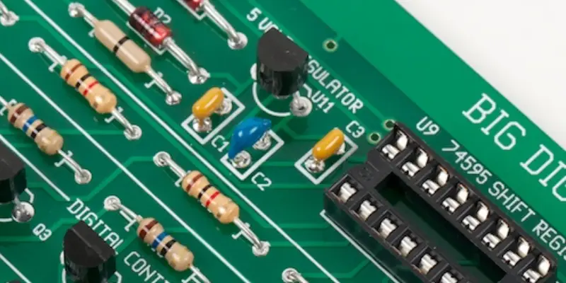
There are two main types of zero ohm resistors: Wire Wound Zero and Surface Mount (SMD). The Wire Wound Zero resistor is easily recognizable by its single black band printed on the body, and it maintains the familiar shape of ordinary resistor kits. While for the Surface Mount Zero ohm resistor, it is a newer approach to minimize costs, reduce PCB covered area, and enhance simplicity.
| Feature | Wire-Wound (Plug-in) | SMD (Surface Mount) |
| Appearance | Single Black Band | Marked “000” or “0” |
| Best For | Prototyping / Manual Soldering | High-speed automated assembly |
| Space Efficiency | Low | High |
The maximum allowable current depends on the package size and power rating:
0402 (1/16W): ~1.1 A
0603 (1/8W): ~1.6 A
0805 (1/4W): ~2.2 A
Top 10 Use Cases of Zero Ohm Resistors
For PCB designers new to these unique components, questions often arise about their usefulness and application. They may be confused about why bother including additional zero-ohm resistors during the manufacturing phase if jumper wires can achieve the same purpose of connecting components on the circuit board. In fact, zero-ohm resistors serve a variety of essential purposes in printed circuit board design and manufacturing, especially in specific scenarios where their advantages become evident. Below we list some common applications for 0 ohm resistors:
1. Debugging and Compatibility
When designing a PCB layout, it is essential to give full consideration to circuit compatibility. Once the PCB has been manufactured, its physical structure and layout cannot be changed. If designers do not adequately address the circuit expandability and compatibility in the future, it’s hard to debug and modify in a later stage. To ensure that a single set of circuit schematics can accommodate future project upgrades and adjustments, designers typically incorporate zero-ohm resistors into the circuit. Below is an example:
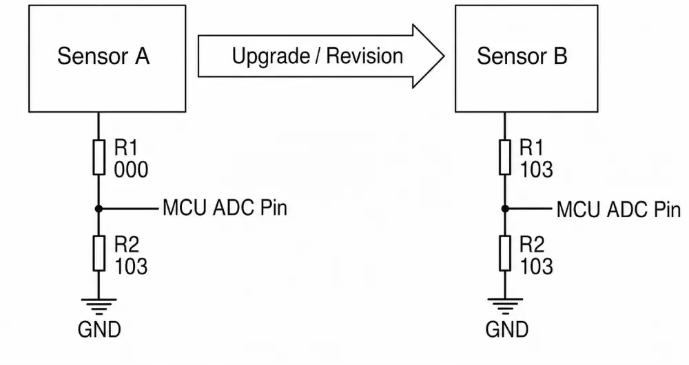
Before upgrade:
The signal from Sensor A goes to the MCU ADC pin through R1 (0Ω), which is almost the same as a wire. The circuit works normally.
After upgrade:
When the circuit is upgraded, Sensor A is replaced by Sensor B. Because the 0-ohm resistor has already been reserved in the design, the back-end MCU ADC can remain unchanged. Thus, the same PCB can support different sensors or different signal routes.
2. PCB Trace Bridging
One of the primary uses of zero ohm resistors is to bridge PCB traces, effectively connecting two points on the board. This can be crucial for joining different sections of a circuit or creating alternate signal paths, enhancing the overall functionality and performance of the electronic system.
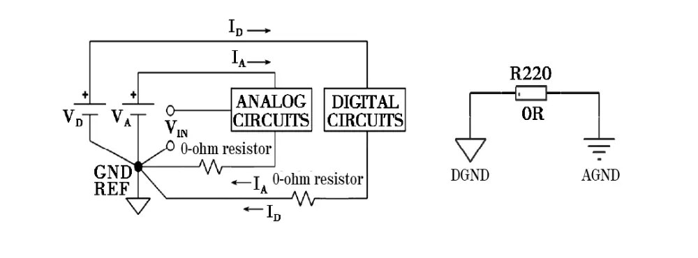
3. Ground Isolation
In PCB layout, AGND and DGND are often routed separately to reduce interference between analog and digital circuits. However, they are not left completely isolated. AGND and DGND are typically connected at a single point. A common approach is to connect AGND and DGND through a 0-ohm resistor, forming a controlled single-point ground connection. This method is generally suitable for low-current circuits, because most 0-ohm chip resistors have limited current-handling capability.
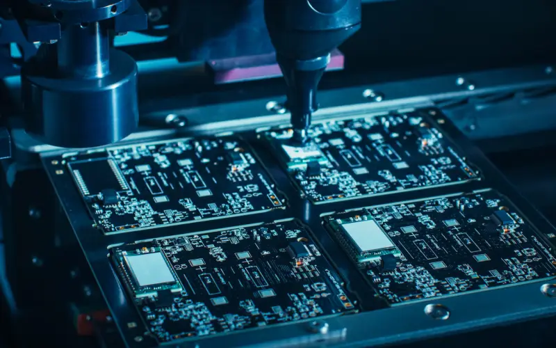
4. SMD Assembly and Automation
In surface mount technology (SMT) assembly processes, zero ohm resistors can be easily placed and soldered by automated pick-and-place machines. Their compatibility with standard SMT equipment streamlines the manufacturing process, which leads to reduced assembly time and costs.
5. Impedance Matching and Signal Integrity
In RF and high-frequency circuits, zero ohm resistors are used for impedance matching. By carefully selecting and placing these resistors, engineers can optimize signal transfer, reduce reflections, and improve signal integrity in critical applications.
6. Temporary Component Placement
Throughout the assembly process or testing phase, zero ohm resistors can serve as convenient placeholders for components. This enables effortless addition or removal of other elements at a later stage, all without requiring any alterations to the PCB layout.
For instance, if you do not confirm the resistance value for a specific location, just reserve a position and install a zero-ohm resistor there. During the later circuit debugging process, replace the o-ohm resistor with an appropriate resistor that has been verified in the reserved location.
7. Fuse Replacement and Over-current Protection
In certain scenarios, 0 ohm resistor can be used as fuse replacements to provide over-current protection. When a fault or excessive current occurs, the zero ohm resistor acts as a sacrificial element, protecting other components from damage. This method offers a more accessible and replaceable solution compared to traditional fuses.
8. Current Shunt and Sensing
Zero ohm resistors can be utilized as current shunts for low-current measurement and sensing applications. What we need to do is measure the voltage drop across the 0 ohm resistor, then, the current flowing through the circuit can be accurately measured.
9. Testing and Debugging
During the testing and debugging phase of PCB development, zero-ohm resistors can be temporarily inserted or removed to isolate specific parts of the circuit, facilitating troubleshooting.
10. Acts as Capacitors or Inductors
In a high-frequency circuit, a 0Ω resistor can behave as a small parasitic capacitor or inductor. This makes it a practical solution for certain electromagnetic compatibility (EMC) issues. For example, a 0Ω resistor can be placed between grounds, or between a power supply and a chip pin.
Benefits of Using 0Ω Resistors
Versatility in circuit design: A 0 ohm resistor has various functions in the circuit that we have discussed above, such as debugging, bridging, and testing.
Compatible with automatic machine: The 0 ohm resistor is replaced with a wire, eliminating the requirement of manual soldering or wiring. During the SMT process, o ohm resistors can be identified with pick-and-place machines, compatible with the automation production line.
Space-saving: In the high-density circuit design, space is critical. While 0Ω chip resistors take up less space, saving up 30% of PCB space with their compact size.
Cost-effective alternatives: Compared with custom routing or discrete jumpers, a 0 ohm resistor is a cost-effective option, priced from $0.002–$0.01 per one.
Design Considerations when Using 0 Ohm Resistor
When using zero-ohm resistors in electronic circuits, engineers need to consider several design considerations, some of which include:
- Current Handling Capacity
0ohm resistors should be selected based on their current handling capacity. Ensure that the chosen resistor can handle the maximum current expected in the circuit without exceeding its power rating or causing excessive heating.
- Power Dissipation
Zero ohm resistors, like any other component, generate heat when current flows through them. During the design process, it’s important to make sure that the power dissipated by the resistor does not dissipate more power than its rated power, even under maximum current conditions.
- Tolerance and Accuracy
Although zero ohm resistors are generally intended to have negligible resistance, they still have some small resistance value due to manufacturing variations. Engineers should consider the resistor’s tolerance and accuracy, especially if precise resistance values are critical in the application.
- SMT Footprint and Assembly
Ensure that the zero ohm resistor has a suitable surface mount technology footprint compatible with the PCB design and assembly process. Double-check the recommended pad layout and soldering guidelines to avoid assembly issues.
- Thermal Considerations
Ensure that the zero ohm resistor is adequately thermally connected to the PCB or surrounding components to dissipate any heat generated. Poor thermal management can lead to increased resistance and component failure.
- PCB Layout and Traces
Zero ohm resistors should be placed on the PCB with careful attention to signal paths, power distribution, and potential noise or interference concerns. The proper layout helps maintain signal integrity and reduces the risk of unintended coupling between traces.
Takeaways
In conclusion, a 0 ohm resistor, despite its seemingly insignificant resistance value, plays a crucial role in the world of electronics. If you’re curious to learn more information about 0 ohm resistors, you can reach out to MOKO Technology. As a leading EMS company in China, we are highly specialized and have sound knowledge in the field of electronic components. Contact us today and discover how zero ohm resistors can elevate the performance and efficiency of your electronic designs.
FAQs
- Is a 0 ohm resistor really 0 ohm?
No, it has a very low resistance. Typically, the resistance value of a zero-ohm resistor falls within the range of approximately 50 mΩ, with a tolerance of ±5%.
- Can a zero-ohm resistor replace a fuse?
Definitely not. A zero-ohm resistor cannot completely replace a fuse. A fuse is designed to melt and disconnect the circuit safely when excessive current flows. A 0-ohm resistor is intended only as a jumper, which may overheat or fail unpredictably under overload conditions.
- 0 ohm resistor vs. jumper wire: What is the difference?
A jumper wire is a piece of conductive wire. A 0-ohm resistor is a PCB component. In some cases, a 0-ohm resistor can replace a wire to increase production efficiency. In the automatic manufacturing process, the pick-and-place machine can identify 0 Ω chip resistors. However, it’s hard to recognize jumper wire, which is also not compatible with automatic manufacturing.
- What does 0 ohmsmean in the circuit?
This commonly shows a reading of 0 ohms on a multimeter. It indicates shorts or direct electrical connections with no resistance in the circuits.