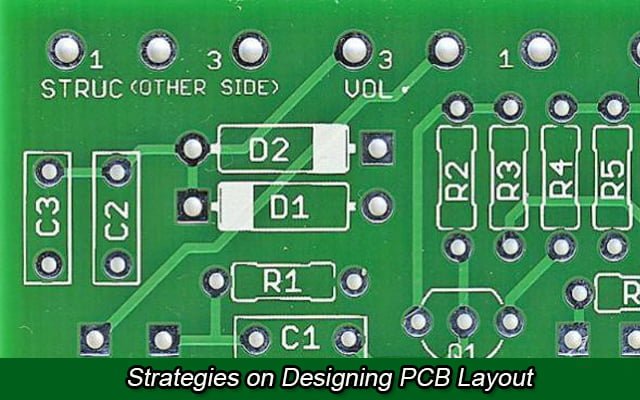
How can I fix the PCB to the mechanical structure?

I designed a PCB with an imaging sensor that is mechanically coupled to a lens assembly using four 2-56 screws. I'm noticing that even though the screws are holding the board tightly against the mechanical structure if I flick or lightly knock the the assembly the image "moves".  I'm hoping to get a few suggestions for ways to fix the PCB to the mechanical structure. Any suggestions for adhesives or the like? Something else?

You probably want to add some mechanical stiffeners to your board. It may be too late for that, however, since that is usually factored into the PCB design (unless you want to design a new PCB and mounting fixture).

The stiffener would be a rigid piece of metal or other material that runs along the length of your PCB (or sometimes across the center of it) with fasteners to hold the board tightly against it. It can also provide the mounting interface to your optics and/or thermal relief (heat sink).

#PCB Assembly #PCB Design
Picture of Oliver Smith

Oliver Smith

Oliver is an experienced electronics engineer skilled in PCB design, analog circuits, embedded systems, and prototyping. His deep knowledge spans schematic capture, firmware coding, simulation, layout, testing, and troubleshooting. Oliver excels at taking projects from concept to mass production using his electrical design talents and mechanical aptitude.

What Others Are Asking

Can I use LEDs without PCB?

I recently purchased LEDs on ebay that were supposed to come attached to star PCB (as a heat sink). The items I received are just the LEDs (no PCB). They are listed as 3W LEDs, with a forward voltage of 3.0-3.4V, and current at 700mA.Will I damage/destroy the LEDs if I use them without a heat sink? If not, what is the best way to mount these to preserve their life during operation?

Why aren’t components in DIP package shipped with straight pins?

I’ve noticed that all DIP packaged devices have pins which are at an angle other than 90∘ and need to be bent so that the angle is right for insertion into holes on the PCB or wherever. Is there any reason other than tradition for that? 

Read Detailed Advice From Blog Articles

PCB vs PCBA: What’s the Difference
Will Li

PCB vs PCBA: What’s the Difference?

PCB and PCBA are the two most common terms in the electronics industry. Although the difference between them is only one letter, they represent different

Strategies on Designing PCB Layout
Ryan Chan

Strategies on Designing PCB Layout

Why PCB Layout is Needed We use Printed Circuit Boards (PCB) for connecting electronic components by using conductive tracks. This allows for prototyping electric circuits

What Is a Solder Bridge in PCB
Will Li

What Is a Solder Bridge on PCB? How to Prevent It?

Flawless PCB soldering is imperative for proper functioning of a printed circuit board. However, even experienced technicians can make small mistakes that lead to soldering defects.

Scroll to Top