They are stand-offs to position the LED above the PCB in a consistent way since the manufacturers often recommend not having the LED directly against the PCB.
Read More: LED PCB Assembly
#PCB Assembly
They are stand-offs to position the LED above the PCB in a consistent way since the manufacturers often recommend not having the LED directly against the PCB.
Read More: LED PCB Assembly
#PCB Assembly
I have a set of LED driving lights for motorcycle that must be wired through a ground-leg pulse width modulation dimmer. The problem is the mounting bracket for the lights is grounded, so the lamp shorts to ground through the motorcycle chassis and the PWM dimmer cant dim the lamps. How do I handle this problem?
According to IPC-7351, the cathode should be on the left for a molded diode. However, when I use component wizard of my suppliers to create a diode, it places the cathode (K) on the right. Does it depend on the manufacturer? How does the assembly house know which way is correct?
I am prototyping a PCB, using Chip Quik’s “SMDSWLF.031, a Sn96.5/ Ag3.0/ Cu0.5 solder with 2.2% no-clean flux. I find that the black spots appears frequently in larger pads on my board. I wonder if it is because I left the soldering iron more time heating the solder and that burnt the flux. What is that black residue? Is that a sign of a bad joint or maybe bad soldering technique?
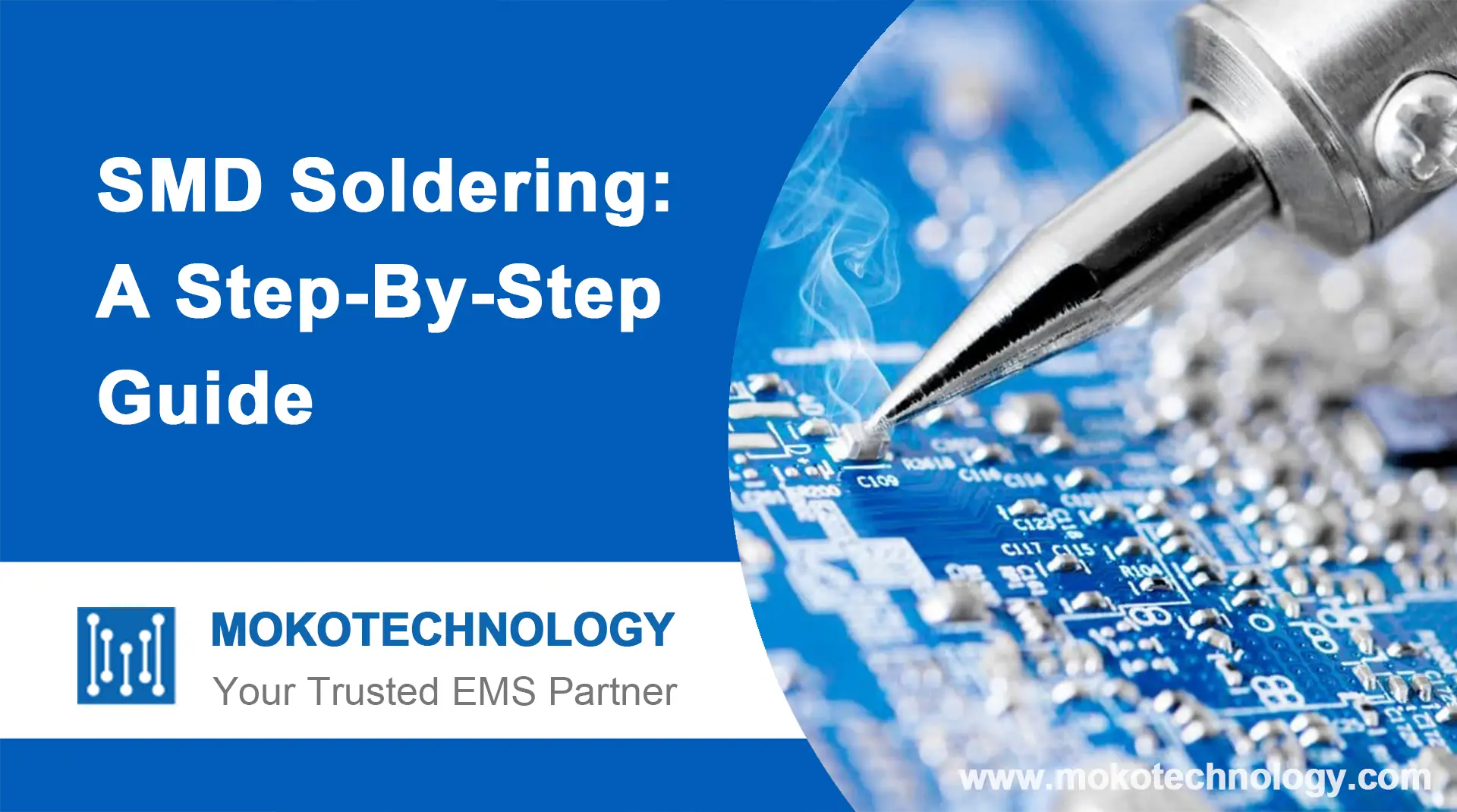
SMD soldering refers to the process of soldering surface mount electronic components to printed circuit boards. As electronic devices and PCBs have gotten progressively smaller,
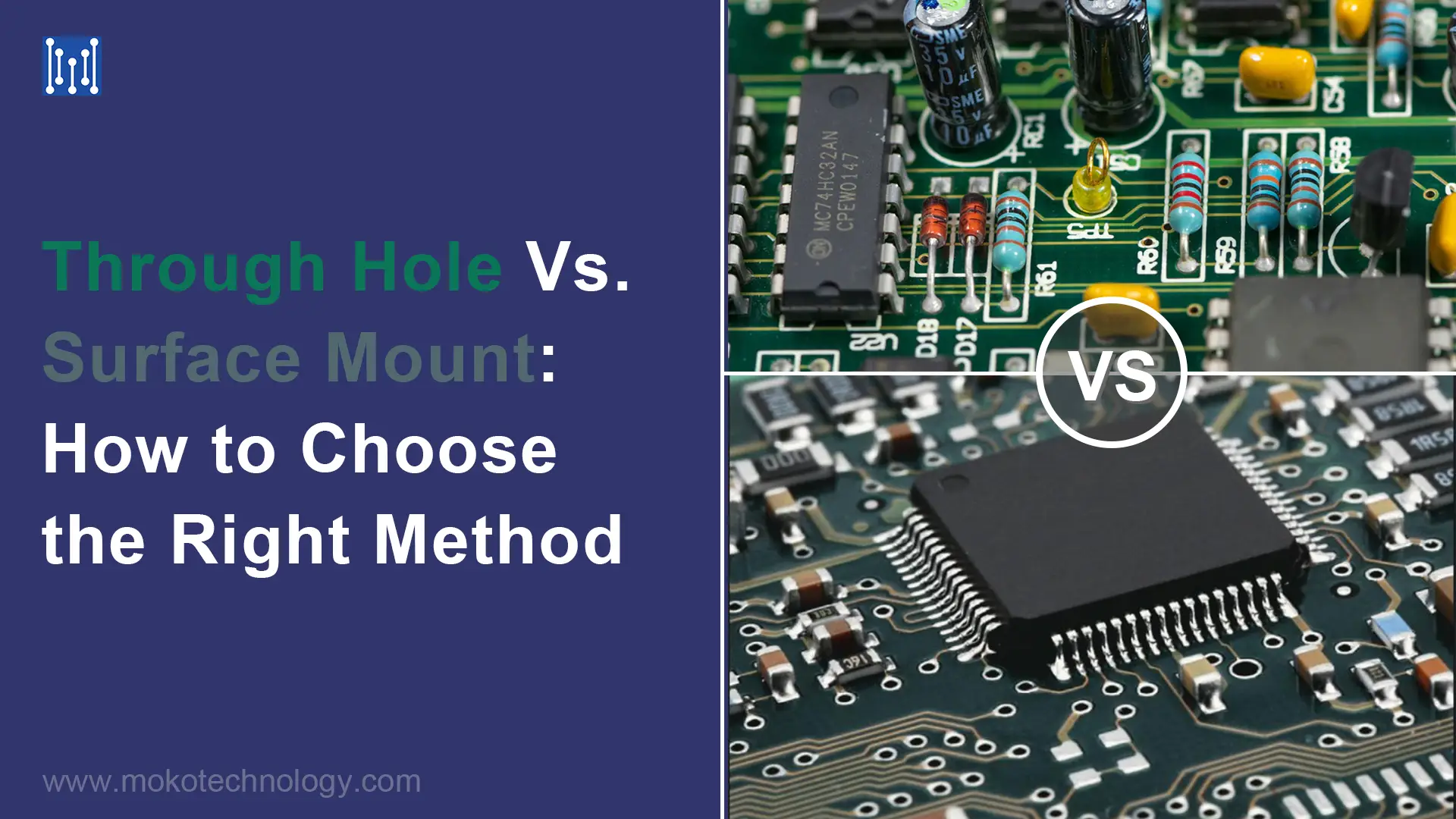
When assembling printed circuit boards, engineers have two main techniques to choose from: through hole and surface mount technology (SMT). In the early days, we dealt
Purchasers and engineers, especially those who have just set foot in this industry, will ask questions after receiving the PCB assembly quotation: What costs are included in
Electronic Manufacturing
Resources
Contact Us
Copyright ©2024 MOKO Technology | Your Trusted EMS Partner 粤ICP备15085690号