As 5G networks roll out globally, they promise to transform connectivity and push the boundaries of what’s possible with mobile technology. But to fully harness the potential of 5G, another less visible technology must keep pace – printed circuit boards (PCBs). 5G PCB is required to achieve superior high-frequency performance while maintaining signal integrity. To reap the full benefits of 5G, PCB manufacturers are rising to the design and production challenges of these essential components. This blog post will delve into the design and engineering considerations for 5G PCB, and explore the manufacturing challenges and innovations involved. Let’s dive right in.
Substrate Materials for Manufacturing 5G PCB
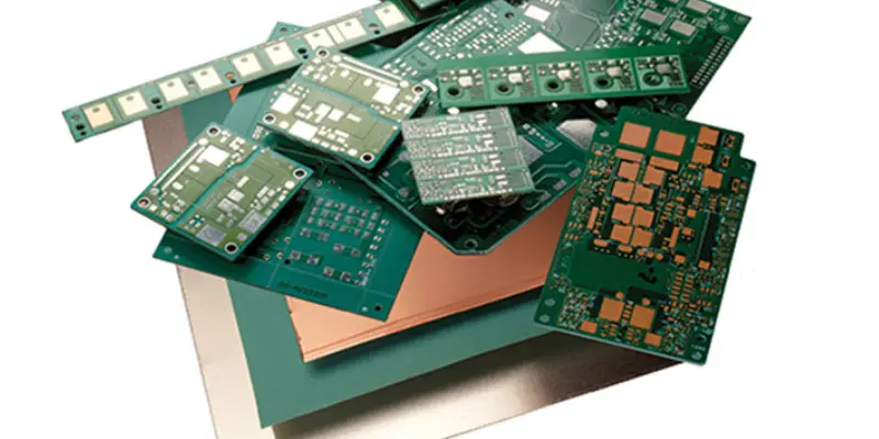
The substrate material is a crucial factor in meeting the performance demands of 5G PCBs. Key parameters to consider when selecting substrates include:
- Dielectric Constant – Lower Dk values around 2-3 reduce signal loss and crosstalk. PTFE and liquid crystal polymer (LCP) are common low Dk options.
- Loss Tangent – Materials with loss tangents below 0.005 like Rogers RO3000 laminates minimize dielectric signal loss at mmWave frequencies.
- Thermal Conductivity – High power density requires dissipating substantial heat. Ceramic aluminum nitride and LCP provide conductivity up to 170 W/mK and 0.67 W/mK respectively.
- CTE– Matching substrate and component CTE prevents solder joint and pad damage from cycling. Glass reinforced hydrocarbons offer CTE compatibility.
- Moisture Absorption–Low moisture absorption behavior in fluoropolymers helps maintain stable electrical performance.
- Thickness – Thinner dielectric layers from 0.1mm to 0.3mm reduce loss, depending on layer count.
Some workable material options include:
- PTFE composites – Offer stable low loss up to mmWave bands and reasonable cost. Allow layer count over 20 layers.
- Ceramic-filled PTFE – Provides the best performance for mmWave applications but at a higher cost. Enables very high frequencies.
- Polyimide – More flexible substrate suitable for thinner PCBs. Moderate loss at high frequencies.
- Aluminum nitride – Exceptional thermal conductivity and low dielectric loss, ideal for high power 5G modules where heat dissipation is critical.
- Liquid crystal polymer (LCP) – Relatively low dielectric constant and loss along with good thermal conductivity.
Challenges of 5G PCB Design
Developing 5G PCBs presents unique difficulties compared to previous generation boards due to the ultra high frequencies and data rates involved. While 5G enables new capabilities, overcoming these design obstacles requires creativity and innovation.
- One major obstacle is integrating mixed signal components on a single board. 5G systems need to operate across a wide frequency range, from MHz to mmWave bands. Capturing and processing such diverse signals on one PCB demands careful planning so that interference and losses are minimized. Striking a balance between analog and digital layout is key.
- Maintaining signal integrity at multi-gigabit data rates also proves tricky. Tighter impedance tolerances must be held, calling for new stackup strategies and thinner copper traces. Routing architectures have to ensure matched lengths between differential pairs to prevent skew. Even small variations can degrade performance.
- Containing EMI presents another roadblock. At microwave frequencies, radiation and coupling risks grow. Thoughtful layout separation between noise-sensitive and noisy circuits is imperative. Shielding components with cans and physical barriers may be necessary as well to confine emissions.
- Thermal issues further complicate matters when dealing with densely packed high-speed components. Carefully selected dielectric materials can help conduct excess heat away from hot chips and traces towards thermal relief structures. Engineering the stackup and plane distribution with thermal needs in mind is vital.
While daunting, these challenges are surmountable through smart design practices. Simulations, prototyping, and design reviews will all help validate performance before manufacturing begins. The end result will be 5G PCBs ready to deliver cutting-edge connectivity.
Tips for 5G Circuit Board Design

Use Low-Loss Dielectric Materials
Using dielectric materials like PTFE (Teflon) or ceramic-filled PTFE is essential for 5G boards in order to minimize signal loss at high frequencies. These materials have a dielectric constant below 3.5, with lower being better to allow tighter trace spacing needed for differential pairs at 5G data rates. The materials should also have a very low loss tangent to prevent excessive signal attenuation.
Maintain Controlled Impedance
With 5G data rates, maintaining 100 Ohm differential impedance is critical for signal integrity. This requires careful trace width and spacing tuning based on the stackup materials being used. Impedance calculators should be followed closely to achieve the target impedance. Electrical lengths between differential pairs must be matched to prevent skew. Stubs or vias on traces should be minimized.
Further reading: How to Achieve Target PCB Impedance Control?
Incorporate Proper Layer Stackup
A solid reference plane should be included next to signal layers for controlled impedance and to provide EMI shielding. Layer count should be kept moderate, around 4-8 layers. Too many layers increase costs and can hamper performance. Symmetric stripline configurations work best, with signal-plane-signal or signal-plane-signal-plane being ideal.
Implement Careful Layout Techniques
Analog and digital sections should be isolated from each other, with coupling prevented through distance and orientation on the layout. Trace lengths should be minimized, using surface mount passives whenever possible. Provide thermal relief under hot components by using thermal vias or slugs. Add EMI shielding structures like cans, guard traces, or moats.
Manage Smooth Layer Transitions
When traces transition between layers, tapers, chamfers, and teardrops should be used to prevent impedance discontinuities that cause signal reflection. The same care should be taken with component pad transitions to inner layers.
Validate Performance with Testing
Test points should be included to use network analyzers, TDRs, and other test equipment to validate impedance, loss, noise over frequency. Thorough automated optical and electrical inspection should also be performed during PCB fabrication to catch any defects.
Applications of 5G Circuit Boards
5G circuit boards will enable much faster data speeds and lower latency for a variety of applications such as:
- Smartphones – 5G circuit boards will enable smartphones to harness faster data speeds and lower latency of 5G networks.
- Tablets – 5G-connected tablets will benefit from ultra high bandwidth for activities like video streaming.
- Wearables – Devices like smartwatches and fitness trackers will leverage 5G boards for always-on connectivity.
- Autonomous Vehicles – Massive data transfer from sensors in self-driving cars requires 5G boards.
- Industrial Automation – Connecting robots, PLCs and sensors wirelessly in factories uses 5G boards.
- Digital Health – 5G PCB can stream high resolution medical imaging and patient data.
- Smart Cities – Infrastructure like traffic monitors and street lights can be connected over 5G.
- Virtual Reality – 5G circuit board facilitates wireless VR headsets with HD video.
- Internet of Things – Connects appliances, meters, trackers over 5G.
Final Thoughts
The emergence of 5G networks represents a new frontier for wireless connectivity, but fully unleashing its potential rests on advancing PCB technology for these cutting-edge systems. While the design and fabrication hurdles are substantial, they are not insurmountable. Through careful material selection, controlled impedance practices, robust layer stackups, thermal management, and rigorous testing, PCB engineers can overcome the challenges and deliver high-performance 5G circuit boards. As materials science and manufacturing processes continue maturing, the capabilities of 5G PCB will only increase.