High speed PCB is a special type of circuit board that can manage billions of operations just in a second. These PCBs achieve this speed using many microprocessors and other robust components. So, any flaw in high frequency PCB board can create a significant problem. Further, it can stop different operations.
Features of High Speed PCB Board
- First of all, the PTH adhesion to copper is not high as a result of the special plate. It is very important to roughen the surface and via using plasma processing equipment such that it increases the adhesion of PTH hole copper and solder resist ink.
- Secondly, it has its relative linewidth control to be very strict. The requirement for impedance control is usually more straight, and also has a general tolerance up to 2 percent.
- Also, it can be roughened using micro-etching water. Hence it can’t be used before the resistance welding else the adhesion would be inferior.
- Equally important, most plates are made using PTFE material. It is vital to correctly use special milling cutters because ordinary cutters produce many burrs.
- And, it has a high electromagnetic frequency, which makes it a special circuit board. If it is above 1GHz, then it can be defined as a high frequency printed circuit board.
Major Applications of High Speed Circuit boards
You can find high Speed printed circuit boards everywhere. It ranges from electronic devices to your handheld devices. The device you are using to read this article uses high speed PCB design.
High-frequency PCB has various uses, some of which include;
- GPS receiver
- Cell phones
- ZigBee
- RF remote control for better signal transmission
- High-speed test equipment
- Ground-based and airborne based radar systems
- Microwave
- Radiofrequency
Signal Integrity Analysis for High Speed PCB
Signal integrity is the quality of the transmitting signal. Manufacturers send this signal on a specific path that can be a wire or an optical device. So signal integrity is to achieve a specific voltage according to your needs.
Different influencing factors for signal integrity
There are two major factors that can affect the integrity of the signals. The first one is the speed of transmitting the signal. And the other one is the length of the transmission medium. Moreover, high speed PCB material can also affect signal integrity. These factors cause a transmission delay. And signal integrity will be affected as a result of a large delay. So, it can affect the performance of circuit boards.
Reflection and solution
Due to the mismatching of impedance, there happens an incomplete absorption of transmitted signal energy. For example, a sudden change of corner can create this issue. Moreover, the incorrect connection of the wire can also lead to reflection. This problem occurs mostly through-hole circuit boards.
When load impedance becomes less as compared to source impedance, it makes reflected voltage negative. As a result, the reverse voltage becomes positive. It also affects the reflection. So, if you want to minimize this effect, you need to reduce reflexes. Matching impedance of the transmission path to both load and source impedance of the signal.
Signal and power-integrity fundamentals
Signal and power integrity are the main factors that become the cause of electronic product’s failure. So it is very important for engineers to be careful while considering analog characteristics of circuitry as different physical phenomena can increase the timing uncertainty of the signals.
All you need to implement PCB paths carefully. Make sure that signals should reach from source to destination in a defined period.
High speed PCB Routing Guidelines
As we know that high speed PCB layout is all about signal integrity. So, you can achieve desired signal integrity by following some unique patterns. These patterns are basically routing guidelines. All high frequency PCB designers have some basic routing techniques in mind.
Importance of Stack up for power integrity
Stacking up plays a key role in power integrity as well as signal integrity. When signal bandwidths increase, you will have to manage the impedance of interconnects. Always make sure that interconnects should terminate. Further, you need to size up your trace to minimize ringing. To achieve this, you need to keep the impedance constant.
Length matching and pair routing
Noise is another major problem that has a severe impact on signal integrity. So, make sure to have sufficient coupling alongside the different pairs. All you need to extend the coupled region to the receiver as much as possible. On the other hand, there should be the same length of uncoupled region and driver in interconnect. This is very helpful to suppress the noise at the receiver.
Importance of choosing right substrate material for PCB
You can improve the rise time by choosing the right substrate material. This material should have flat dispersion and contains lower loss tangent. Dispersion is crucial here. Because it is very helpful in changing propagation constant and impedance along interconnect. In addition, it also propagates the electromagnetic pulses.
High Speed PCB Materials
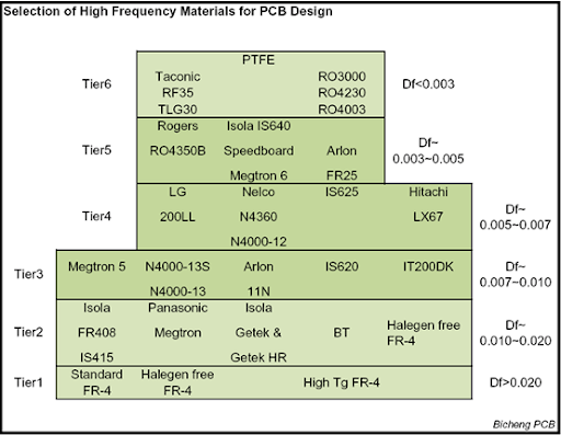
- Rogers 4350B HF
- Rogers RO3001
- Rogers RO3003
- Taconic RF – 35 Ceramic
- Taconic TLX
- ISOLA IS620E – Fiberglass
- ARLON 85N
| Material for high-frequency boards | Rogers RO3003 |
| T | – |
| CTE-z | 25 |
| Er | 3.0 |
| Electric strength | – |
| Surface resistivity | 1×10^7 |
| Thermal conductivity | 0.50 |
| Dk loss Tangent | 0.0013 |
| Td value | 500° |
| Peel Strength | 2.2 |
| Materials for high-frequency boards | Rogers RO3006 |
| Tg | – |
| CTE-z | 24 |
| Er | 6.2 |
| Electric strength | – |
| Surface resistivity | 1×10^5 |
| Thermal conductivity | 0.79 |
| Dk loss Tangent | 0.0020 |
| Td value | 500° |
| Peel strength | 1.2 |
| Material for high-frequency boards | ARLON 85N |
| Tg | 250° |
| CTE-z | 55 |
| Er | 4.2* |
| Electric strength | 57 |
| Surface resistivity | 1.6×10^9 |
| Thermal conductivity | 0.20 |
| Dk loss Tangent | 0.0100° |
| Td value | 387° |
| Peel strength | 1.2 |
| Materials of high-frequency boards | Rogers RO3001 |
| Tg | 160° |
| CTE-z | – |
| Er | 2.3 |
| Electric strength | 98 |
| Surface resistivity | 1×10^9 |
| Thermal conductivity | 0.22 |
| Dk loss Tangent | 0.0030 |
| Td value | – |
| Peel strength | 2.1 |
| Material for high-frequency boards | ISOLA IS620 E-fiber glass |
| Tg | 220° |
| CTE-z | 55 |
| Er | 4.5* |
| Electric strength | – |
| Surface resistivity | 2.8×10^6 |
| Thermal conductivity | – |
| Dk loss Tangent | 0.0080 |
| Td value | – |
| Peel strength | 1.2 |
| Materials for high-frequency boards | Taconic RF-35 Ceramic |
| Tg | 315° |
| CTE-z | 64 |
| Er | 3.5** |
| Electric strength | – |
| Surface resistivity | 1.5×10^8 |
| Thermal conductivity | 0.24 |
| Dk loss Tangent | 0.0018** |
| Td value | – |
| Peel strength | 1.8 |
| Material for high-frequency boards | Taconic TLX |
| Tg | – |
| CTE-z | 135 |
| Er | 2.5 |
| Electric strength | – |
| Surface resistivity | 1×10^7 |
| Thermal conductivity | 0.19 |
| Dk loss Tangent | 0.0019 |
| Td value | – |
| Peel strength | 2.1 |
Final words
High speed printed circuit boards are the need of the most efficient devices. Everyone wants fast devices. The speed of any device depends on its circuit board and high frequency PCB boards depend on signal and power integrity. To achieve the maximum speed, you need high speed boards. And it is essential for all high frequency PCB manufacturers to control the quality strictly to meet their client’s needs. If you’re looking for a manufacturer that can assure you with high-quality PCB boards, then contact us now!