Does anyone know of a surface-mount component that could work as an Infrared Radiation barrier?

I have a PCB design that uses an infrared proximity detector in the form of an IR LED and an IR transistor placed with about 10 mm spacing between them. Now the problem has arisen that I need some sort of physical barrier between them to prevent crosstalk and false proximity detections.
  • Try SMD 0.1″ headers. Pick & Place and wave soldering are compatible, but these need a minimum of 3 pins due to the alternating SMD feet to keep them standing before the solder holds them on.
  • Switch to an transistoror diode pair that already comes with a molded body, unless those don’t exist in SMD.

Read More: LED PCB Assembly

#PCB Design
Picture of Oliver Smith

Oliver Smith

Oliver is an experienced electronics engineer skilled in PCB design, analog circuits, embedded systems, and prototyping. His deep knowledge spans schematic capture, firmware coding, simulation, layout, testing, and troubleshooting. Oliver excels at taking projects from concept to mass production using his electrical design talents and mechanical aptitude.

What Others Are Asking

Can leaded BGA chips be reflow soldered with lead-free process?

I know that using leaded process for lead-free BGA chips is not acceptable, because the solder balls of the BGA will not melt and the joint will be unreliable. But now BGA chip is only available in lead-free balls. is it ok to solder leaded BGA chips with a lead-free (thus, higher temperature) process?

Why aren’t components in DIP package shipped with straight pins?

I’ve noticed that all DIP packaged devices have pins which are at an angle other than 90∘ and need to be bent so that the angle is right for insertion into holes on the PCB or wherever. Is there any reason other than tradition for that? 

Read Detailed Advice From Blog Articles

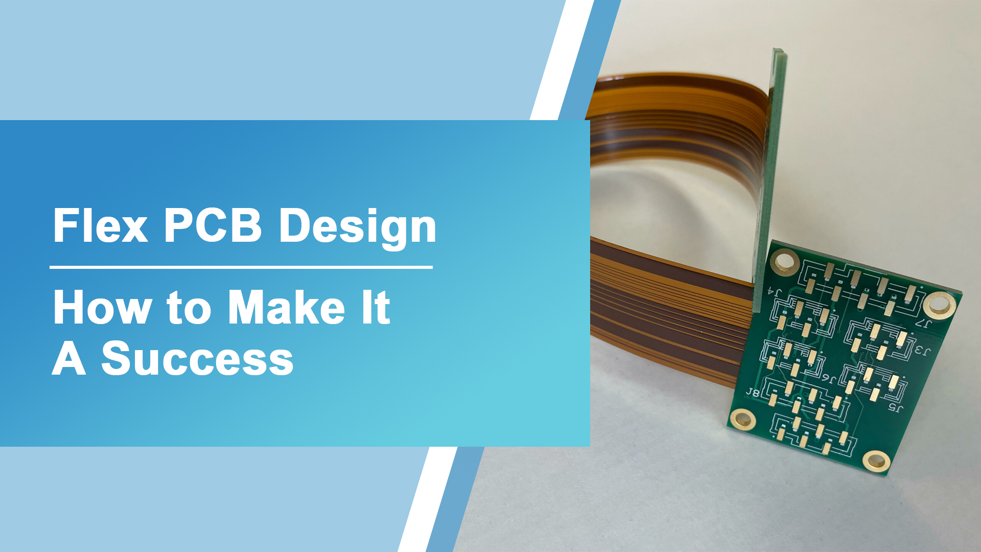
Flex PCB Design
Ryan Chan

Flex PCB Design- How to Make It A Success

Flex PCBs, or Flexible Printed Circuit Boards, have gained significant popularity in recent years due to their unique properties and advantages in various applications. These

Scroll to Top