- VISUAL INSPECTION
- IN-CIRCUIT TESTING (ICT)
- FLYING PROBE TESTING(FPT)
- AUTOMATED OPTICAL INSPECTION (AOI)
- AUTOMATED X-RAY INSPECTION(AXI)
- FUNCTIONAL TESTING (FCT)
- BURN-IN TESTING
#PCB Manufacturing #PCB Assembly #PCB Testing

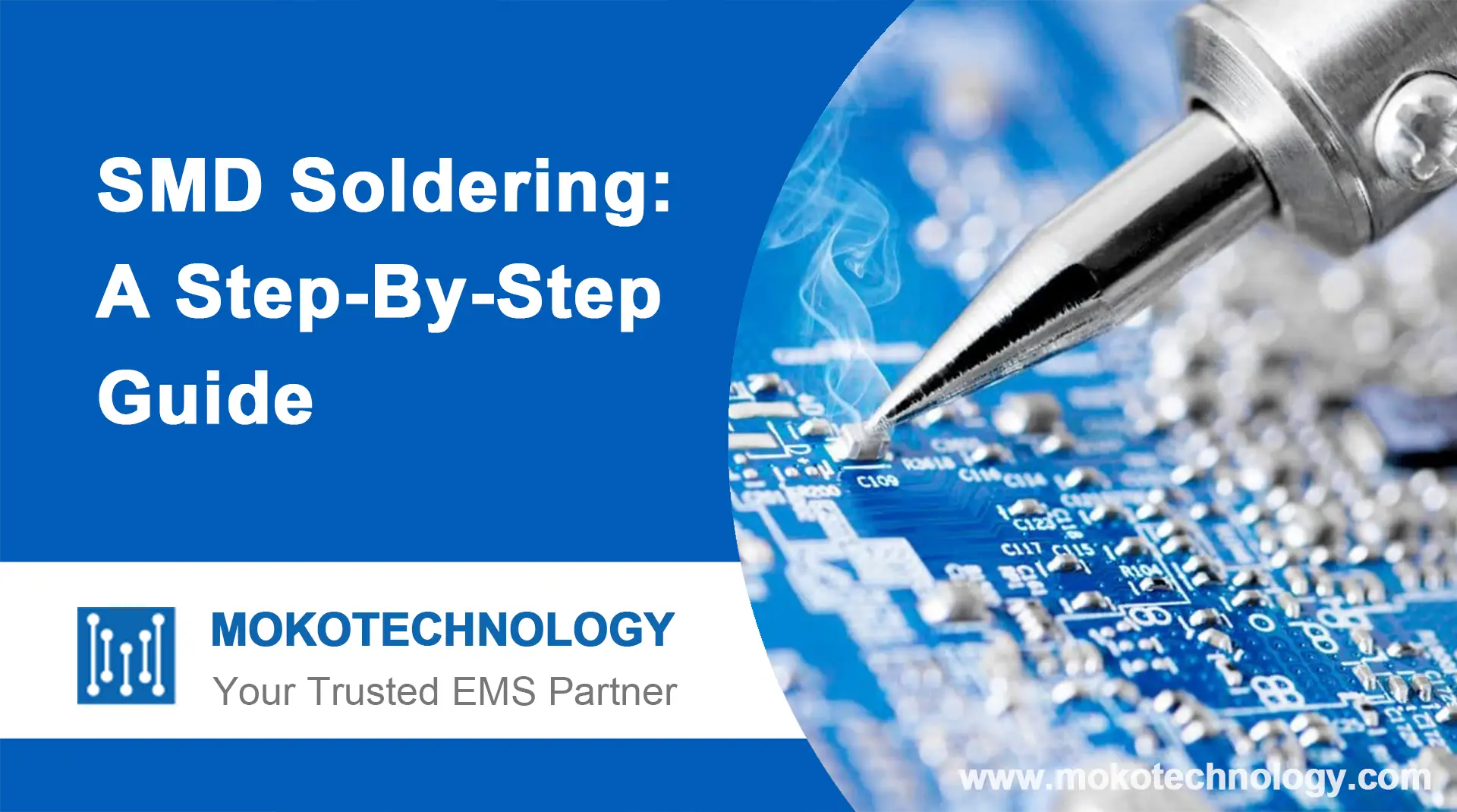
SMD soldering refers to the process of soldering surface mount electronic components to printed circuit boards. As electronic devices and PCBs have gotten progressively smaller,
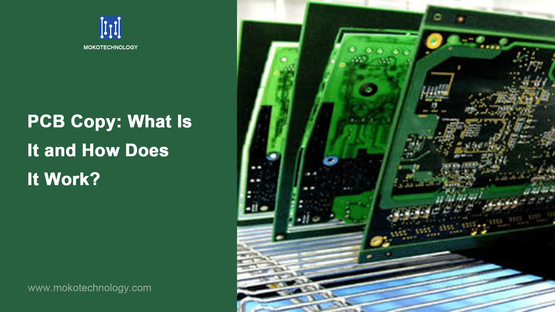
PCB copy has become increasingly popular in recent years as it enables manufacturers to copy existing PCB designs, components, etc. to create a new identical
In times of difficulty to obtain components, increasing demand for flexibility and fast development cycles, clean and inexpensive PCB rework to save assembled or bare
