In times of difficulty to obtain components, increasing demand for flexibility and fast development cycles, clean and inexpensive PCB rework to save assembled or bare printed circuit boards are becoming increasingly important. Every PCB or PCB assembly that can be repaired by rework protects our environment by not disposing of it and by not having to produce new PCBs. MOKO Technology has saved more than 500,000 PCBs in recent years.
Using special, self-developed techniques, the experts at MOKO Technology can, for example, drill holes into previously assembled assemblies. The accuracy corresponds to the newly produced printed circuit boards. The work is only carried out by employees with many years of experience in PCB fabrication. State-of-the-art measuring technology enables optimal monitoring of the work. Depending on the amount and complexity of the rework, the delivery time is usually less than five working days after receipt of the goods. An express service is also available for urgent PCB rework, where it is possible to carry out reworking within a few hours.
PCB Rework assembled boards
Unsolder and then solder in again
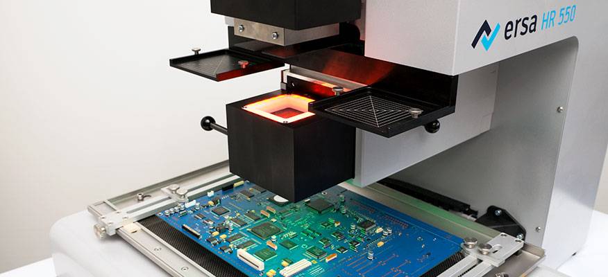
In order to solve the special problems to the satisfaction of customers in the long term, MOKO Technology has invested in equipment. The focus here was on simple and gentle material removal and re-soldering of components. The choice fell on the Ersascope 1 and the PCB rework system IR 550 A from Kurtz Ersa. At MOKO Technology, particular care was taken to ensure that the circuit board was heated as homogeneously as possible. We keep the thermal stress on the boards as low as possible during the PCB rework process. As a result, we do not unnecessarily impair the lifespan of the printed circuit boards and components. The repair and refitting then take place both manually and with mechanical support.
The IR 550 A rework system heats the PCB homogeneously using medium-wave infrared emitters (4 µm to 8 µm). Warming up the assembly is important to prevent the PCBs from warping and to achieve a low-temperature gradient ΔT from the top of the PCB to the bottom.
The top heating in the Ersa systems is also designed as a medium-wave infrared heater or hybrid heater. The hybrid heater is an infrared heater with a low degree of convection. This way we can also achieve a low horizontal temperature gradient, i.e. across the component, from corner to corner. Furthermore, we avoid hot spots due to too much hot air and reduce the blowing away of neighboring, unsecured components.
Automated desoldering during PCB rework
In every process during PCB rework, a sensor records the temperature directly on the component. A closed control loop controls and controls the soldering process, which should minimize the risk of temperature deviations and the associated stress for the components and circuit board. Our employees also work in a controlled manner when picking up components from the circuit board. The IR 550 A from Kurtz Ersa is equipped with a vacuum pipette integrated into the top radiator. This enables the desoldering process to be automated. The attached vacuum suction cup automatically lifts the component off the board as soon as the solder has melted. This careful picking up the component prevents any stress on the circuit board.
These gentle processes are particularly in demand for package-on-package applications. When soldering in and out, the requirements for the homogeneity of the heat distribution are particularly high. For example, both levels can be edited at the same time. Components lying one above the other can be lifted off together after the solder melt. The same applies to the re-soldering of the components. These can be placed and soldered together, which simplifies the overall process.
If separate processing of the levels is necessary, this is also possible. To do this, the temperature profile must be set very precisely, for example, to desolder only at the top level. In this case, too, the components on the upper level can be repositioned and soldered in again. It is advisable to use the RPC 500 reflow process camera to observe the solder melt on both levels.
The Ersascope 1 vision system is recommended for checking the results of all rework, but especially when reworking BGAs (see lead image). In conjunction with another X-ray analysis or other data, the quality of the solder joints can be checked visually. Bridges, contamination or anomalies under the component can be identified in this way.
Special tasks in PCB rework services
A high level of expertise and modern equipment are absolutely necessary for the professional handling of rework. When it comes to special tasks such as package-on-package or wiring under BGAs, tact, experience and the right technical equipment are crucial. MOKO Technology has been performing PCBA and PCB manufacturing since 2006, so we’re already very experienced in handling the PCB rework. We confirm that special tasks have also come up to the Chinese specialists over the years. Initially, the inquiries were manageable, but over time we have built up a good reputation for special tasks so that we are dealing with increasingly demanding tasks that have been and will be entrusted. Our main task is not just standardized soldering and re-soldering of components. We often save the entire circuit board with our work, which means that our customers can meet their delivery dates and avoid unnecessary costs.
One of the supreme disciplines is the wiring underneath a BGA. If the development of high-priced electronics has been improper, these assembled circuit boards end up with us. This means that connections for BGAs were mostly forgotten. Due to the high packing density on the printed circuit boards and the increasing miniaturization of the components, we first have to check every request for technical feasibility. If it is possible to set a wire bridge, the component must be unsoldered. Then the printed circuit board and the solder pads must be freed of tin and the surface to be processed must be cleaned of all disruptive factors. The wire jumpers are then pulled by hand, requiring the highest precision. It is particularly important to select the correct wire size, otherwise short circuits may occur when touching the BGA balls. The components are then re-set and soldered. The soldering process must be closely monitored using camera monitoring. This is followed by an X-ray analysis of the revised area.
According to the managing director from our company, monitoring the soldering process during rework is a necessity. We generally carry out a solder joint analysis for these tasks in order to also define the soldering profile for the subsequent work. Camera surveillance is a crucial support. The first analysis is made with the endoscope, followed by more precise results on the X-ray. This is the only way we can guarantee our customers high-quality PCB rework. In the package-on-package area, the experience gained in reworking and the machines used for this are used. It does not matter whether rework is carried out or the customer wants to have components assembled using the package-on-package procedure. The tasks are very similar. In the package-on-package area, the BGA must also be precisely placed and soldered. The soldering is also checked by means of a solder joint analysis to avoid errors and to create an exact soldering profile for the customer and the subsequent tasks.
The Ersa IR 550 A PCB rework system heats the circuit board homogeneously using medium-wave infrared emitters (4–8 µm). This prevents local overheating, so-called hot spots. Warming up the assembly is particularly important to avoid warping the PCB and to achieve a low, vertical Delta T, i.e. a temperature difference on the top of the PCB from the bottom of the PCB. The top heating in our Ersa systems is also designed as a medium-wave infrared heater or hybrid heater. The hybrid heater is an infrared heater with a low degree of convection. We can also achieve a low, horizontal delta T across the component, from corner to corner. We also avoid hot spots due to too much hot air and we reduce the blowing away of neighboring, unsecured components.
The temperature is recorded in every process by a sensor directly on the component. The soldering process is controlled and controlled via a closed control loop, which minimizes the risk of temperature deviations and the associated stress for the components and printed circuit board. Our team works just as easy and in a controlled manner when picking up components from the circuit board. The Ersa IR 550 A is equipped with a vacuum pipette integrated into the top radiator, which allows the desoldering process to be automated. With the vacuum cup attached, the component is automatically lifted off the board as soon as the solder has melted. By carefully picking up the component, we avoid any stress on the circuit board.
These gentle processes are particularly in demand for package-on-package applications. The requirements for the homogeneity of the heat distribution are particularly high here, especially when soldering and desoldering. For example, both levels can be edited at the same time. Components lying one above the other can be lifted off together after the solder melt. The same applies to re-soldering the components. Joint placement and joint soldering are possible and simplify the overall process, as the management of MOKO Technology confirmed on request.
If separate processing of the levels is necessary, this is also possible. To do this, the temperature profile must be set very precisely, e.g. just desolder the top level. The subsequent placement and re-soldering of the components on the upper level are also possible. The use of the reflow process camera (RPC) makes sense to observe the solder melt on both levels.
The Ersascope 1 vision system is recommended for checking the results of all rework, but especially when reworking BGAs. In conjunction with another X-ray analysis or other data, the quality of the solder joints can be checked visually. Bridges, contamination or anomalies under the component can be identified.