
From the moment you turn your ignition key, automotive PCBs are quietly at work in your car — from its safety systems to the split-second decisions they make. The automotive PCB market is projected to expand from USD 12.22 billion in 2025 to USD 16.91 billion by 2031, with a CAGR of 5.56%. This guide explains automotive PCB types, applications, design considerations, and the differences between automotive PCBs and standard PCBs.
What Is an Automotive PCB?
An automotive PCB is a printed circuit board that is specifically designed for use in automotive electronic systems. From simple lighting systems to sophisticated infotainment and safety equipment, all of these rely on automotive PCBs for power. Automotive PCBs need to withstand harsh conditions, such as extreme temperature fluctuations, vibrations, and humidity, while also meeting the high reliability standards set by the automotive industry.
Automotive PCB vs. Standard PCB: What’s the Difference?
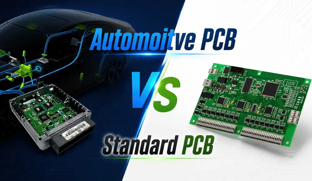
1. Material Selection
Typically, standard PCBs are made of FR-4 fiberglass, which is relatively cost-effective and can meet the demands of most electronic products. Automotive PCBs are constructed from more sophisticated composite materials designed to handle extreme heat, high humidity, and electrical noise generated by the car.
2. Manufacturing Standards
All automotive PCBs are manufactured to a high-quality standard, based on the IATF 16949 standard. The soldering, protective coating, fire resistance and corrosion resistance process and requirements are stricter in their production compared to the production of standard PCBs.
3. Board Thickness
The thickness of standard PCBs are usually 0.2 mm to 3.0 mm and the automotive PCBs are normally produced with a thickness range of 0.6 mm to 3.2 mm. The thicker board construction can enhance mechanical strength and reliability in extreme operating conditions,
4. Reliability Requirements
The reliability requirements of the automotive PCB boards are higher than that of the normal PCB boards. They have to undergo a series of tests to demonstrate their resistance to aging, corrosion, and other challenges they may encounter in extreme environments.
Here’s a side-by-side comparison of their key performance specifications:
| Feature | Standard PCB | Automotive-Grade PCB |
| Board Thickness | 0.2 – 3.0 mm | 0.6 – 3.2 mm |
| Temperature Range | −20°C ~ 105°C | −40°C ~ 150°C |
| Vibration Tolerance | 5G | 10G |
| Service Life | 3–5 years | 15+ years |
| Defect Tolerance | 500 ppm | <0.1 ppm |
| Corrosion Resistance | 48h neutral salt spray | 1,000h acidic salt spray |
6 Automotive PCB Types and Their Features
There are 6 types of printed circuit boards that are widely used in the automotive industry:
1. Ceramic PCB: The core of ceramic-substrate circuit boards is made of aluminum nitride or alumina. It has features with great thermal conductivity and high-temperature resistance.
2. HDI PCB: Compared to traditional circuit boards, HDI PCB has a higher wiring density. It contains blind/buried microvias, and the minimum space of HDI PCBs used for automobiles is about 75μm/75μm or smaller.
3. High-frequency PCB: High-frequency PCBs are commonly used in car collision avoidance or predictive emergency braking systems, which rely on the PCB to transmit microwave high-frequency signals. While PTFE or hybrid ceramics are perfect choices for high frequency PCB materials, they feature low dielectric loss and can be used as high frequency wave transmitters and receivers.
4. Flexible PCB: This kind of circuit board has the advantage of foldability. It is estimated that there are more than 100 flexible PCBs are used in an automobile, in addition, it becomes a trend to use flexible PCBs to replace the harnesses.
5. Rigid-flex PCB: Rigid-flex PCBs are much popular in the automotive industry, and widely used in automotive LED lighting systems. They combine the advantages of rigid PCB and flexible PCB and reduce solder joints and connectors.
6. Metal substrate PCB: The substrate of metal PCB is normally made of aluminum or copper. Compare to traditional PCBs like FR4 PCB, it has better thermal conductivity.
Applications of Automotive PCB
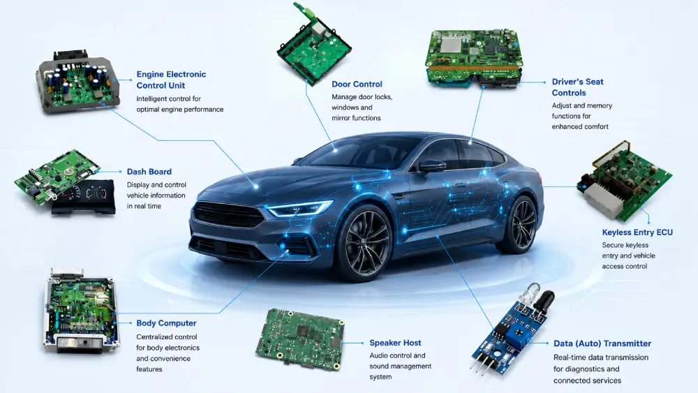
We can find automotive PCBs almost everywhere in a car. Here are some common applications:
- GPS Systems
Modern cars are basically equipped with GPS navigation systems. By using it, we can travel freely in the streets and alleys and arrive at the destination accurately even in an unfamiliar city, and this very useful and widely used system is driven by automotive PCBs.
- Control and Information Systems
The intelligent control and monitoring system on the car also uses a large number of complex PCBs to transmit fuel reserve, brake light, and speed light information to the instrument panel, so that the driver can operate better and safer.
- Near Field Monitors
Near-field monitors can reduce blind spots for drivers and help drivers to control their vehicles better, they can reverse and park more easily. And all near-field monitors use automotive printed circuit boards to transmit the signal.
- Audio/video equipment
Today’s cars are given more functions, most of them are equipped with audio and video equipment, and the core of the operation of such equipment is PCB. Audio and video equipment can provide drivers with a better driving experience, for example, they can listen to music while driving.
- LED Lighting System
For automobiles, LED lights can not only provide lighting functions but also can create different styles of the vehicle and add personality. LED lights are featured with a longer lifespan and lighting efficiency, and PCBs play a critical role in their operation.
Automotive PCB Design Guidelines
Due to high industry standards and the special application environments, we must take automotive PCB designs seriously to make sure that they can perform as expected. In this part, we have listed a few factors that should be considered when designing an automotive PCB:
- Inductor Orientation
The inductance will be generated when two inductors or two PCB wires come close to each other. By designing a compact circuit layout and reducing the coupling balance, we can achieve optimal placement of all inductors in the circuit. And there are 2 basic rules to follow when designing automotive printed circuit boards: First, the spaces between the inductors should be designed as large as possible; second, we need to design the inductor alignment at right angles that can minimize the inductor crosstalk.
- Lead Coupling
Mutual inductance occurs and affects coupling when leads are placed close. In this case, the return current path should be designed as close as possible to the main current path, while reducing the radiated field to reduce the current loop area. Considering the integrated ground under the leads whenever possible during the design process can improve the performance of automotive printed circuit boards.
- Grounding thru-hole
In terms of grounding thru-hole, when designing the circuit layout of an automotive PCB, we should notice that thinner PCB copper will reduce the effect of parasitic inductance of the via, and vias in sensitive areas should establish inductance module.
- Grounding and Filling
Grounding and filling are important aspects of automotive PCB design, and proper design can avoid impedance issues in the circuit. During the design process, the following points must be considered: First, it is necessary to provide a continuous ground area with very low impedance. Second, the filler wire terminals and via arrays need to be connected to ground. Finally, ground the copper clad wire.
- Signal Integrity
Proper routing of signals on the PCB is crucial for signal integrity in automotive applications. Use controlled impedance traces, minimizing trace lengths, differential signaling, isolating analog/digital signals, and proper ground planes. This prevents reflections, interference and maintains signal quality.
- Thermal Management
Effective thermal management is crucial as automotive PCBs often handle high power levels. Conduct thermal analysis to pinpoint hot spots, and implement solutions like copper heat sinking planes, thermal adhesives, strategic component placement, and heat dissipation vias. This enables heat to spread and avoid localized build-up that degrades components.
- Meeting Automotive Design Standards
Compliance with automotive design standards is imperative to ensure safety, dependability, and conformity with regulations. Familiarize yourself with relevant standards like:
ISO 26262: Functional safety standard for electrical and electronic systems.
EMC Standards: Regulations related to electromagnetic compatibility (e.g., CISPR 25 and ISO 11452).
Automotive Environmental Standards: Standards governing environmental factors, including temperature, humidity, and vibration (e.g., ISO 16750).
- Optimize RF circuit
Automotive wireless functionality relies on optimizing RF PCB performance through controlled impedance dimensions, short trace lengths, shielding, proper components, and matched interfaces. Extensive modeling, prototyping and tuning will align the RF circuits to meet the demanding wireless needs of the vehicle.
Working with a Professional Automotive PCB Manufacturer
Want to start your automotive PCB project? Find a professional automotive PCB manufacturer is critical if you lack professional PCB design and manufacturing knowledge.
MOKO Technology, as one of the leading PCB manufacturers in China, has nearly 20 years of experience for automotive PCB manufacturing and assembly. All automotive PCBs, from HDI PCBs, flex-rigid PCBs, flexible PCBs, to metal core PCBs are manufactured and assembled to the highest industry standards to ensure that they are safe and reliable. Contact us today to get a free quote!
FAQs about Automotive Circuit Boards
- What is an automotive PCB board?
An automotive PCB is a specific type of circuit board used in automobiles. Its applications span engine control units (ECUs), Advanced Driver Assistance Systems (ADAS) sensors, infotainment systems, and EV Battery Management Systems.
- What are the main differences between automotive-grade and consumer-grade PCBs?
The quality of automotive-grade PCBs is much higher than it is for the consumer PCBs — wider temperature range, higher vibration resistance, longer service life, and much stricter defect tolerance.
- What certifications should an automotive PCB manufacturer have?
IATF 16949 is the most important certification for automotive PCBs, as it specifies the automotive industry’s quality management requirements. Other significant certifications include ISO 26262, ISO 9001, RoHS compliance, and ISO 16750.
- How are automotive PCBs tested for reliability?
Usually the tests performed are thermal cycling tests, vibration mechanical shock tests and salt water spray tests (up to 1,000 hours). On the inspection side, it is done by combining the testing methods of AOI, AXI and flying-probe testing.