When it comes to electronics, PCBs are the unsung heroes that make everything work together smoothly. They’re like the roads that connect all the parts of a city, letting signals travel where they need to go. And just like you want roads made of reliable materials that can handle the traffic, you want your PCBs built tough. The PCB material you choose is important. It determines how well your device will perform and hold up through day-to-day use. Fortunately, a diverse array of materials is at your disposal, catering to your specific design performance needs. This guide will take you through the main PCB materials you can pick from and what makes each one unique. So let’s get to it!
What Are Circuit Boards Made Of?
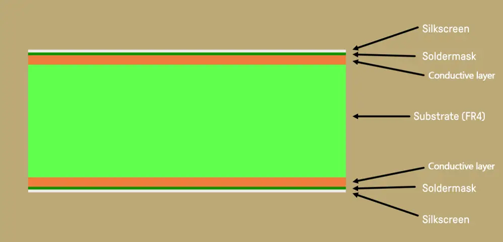
In this section, we mainly introduce the key layers that make up the PCB and the materials they use:
- Substrate layer
The PCB substrate layer is like the foundation of a house – it’s the base that everything else in a printed circuit board builds on top of. Usually, this layer is made from fiberglass, which gives PCBs their signature rigidity. But fiberglass isn’t the only material out there.
Substrates can also be constructed using epoxies, CEM-1, G-11, insulated metal, FR-1, or polyimide. Each material has its own properties that engineers choose depending on things like how much heat the PCB can handle or the dielectric constant. But out of all the options, FR-4 is by far the most popular.
- Conductive layer
If the substrate layer is the foundation of a printed circuit board, you can think of the conductive layer as the wiring that makes everything run. This is the layer made up of thin copper traces that transmit signals and power throughout the circuit.
Copper has become the go-to material for the conductive layer because it’s an excellent conductor and more affordable than other options like silver or gold. Sure, those materials are a bit more conductive, but copper gets the job done for most applications.
The conductive traces on a PCB are like tiny copper highways carrying electricity to all the different components. The layout and design of these traces are super important to making sure signals can travel fast and efficiently.
- Solder mask layer
The solder mask layer, a thin plastic-like coating, is placed over the copper tracks on a PCB board. This layer acts as an insulator that stops solder from bridging between nearby copper tracks when the PCB is being assembled. The solder mask therefore plays a key role in preventing unwanted electrical connections from forming. By only exposing intended solder points, the solder mask guides the solder to make proper connections and avoid short circuits. And there are actually a few different materials used for solder mask depending on the application method, they are epoxy liquid, dry film, and liquid photoimageable.
- Silkscreen layer
The silkscreen layer on a printed circuit board is like a road map for building the electronics. This epoxy ink gets printed on top of the PCB in the final stages. It shows where each component should be placed with helpful labels and markings. Beyond labeling, the silkscreen also indicates important warnings or logos from the manufacturer. All those little symbols and codes printed in white ink provide crucial guidance for construction and debugging.
Common Types of PCB Material
- FR-4 (Flame Retardant 4)
FR-4 has become the predominant material for printed circuit boards because of its optimal combination of affordable pricing, reliable performance, and manufacturing simplicity. It’s composed of a woven fiberglass cloth impregnated with epoxy resin and reinforced with a flame-retardant material. FR-4 printed circuit boards provide effective electrical isolation and structural robustness while remaining functionally stable across high and low temperatures. This versatility makes FR-4 a fitting choice for PCBs in various products including consumer electronics, telecommunications devices, and industrial machinery.
- CEM-3
Like FR-4, CEM-3 is made from woven glass fibers soaked in an epoxy resin. This gives it many of the same desirable properties as FR-4: excellent electrical insulation, mechanical strength, and thermal stability. But CEM-3 distinguishes itself by being a bit more affordable. For circuit designs that don’t need the absolute pinnacle of performance, cost-conscious engineers often reach for CEM-3 instead of the pricier FR-4. So while venerable FR-4 still reigns supreme for advanced applications, CEM-3 offers an enticing option for more everyday PCB needs. Its balance of capabilities and modest price point make CEM-3 a reliable backend material for all kinds of electronics.
- Polyimide
Polyimide is a versatile polymeric material ideal for printed circuit boards in demanding environments. Polyimide’s unmatched thermal stability, mechanical flexibility, and chemical resistance enable it to maintain its integrity and functionality even when subjected to intensely demanding operational environments. While extreme heat and caustic agents compromise the robustness of many materials, polyimide retains its properties and continues to perform reliably.
This exceptional thermal and chemical resilience, paired with structural flexibility, makes polyimide well-suited for mission-critical electronics across many industries, including aerospace, automotive, and military.
- Teflon (PTFE)
This material offers exceptional electrical qualities that minimize signal loss, even at radar and satellite frequencies. PTFE’s star attractions are its low dielectric constant and loss tangent, which limit signal degradation and distortion. It also has outstanding thermal stability thanks to its high glass transition temperature. Teflon PCBs maintain their structure and performance integrity even when exposed to extreme heat. To top it off, this PCB material exhibits superb chemical resistance, shrugging off even harsh chemicals that would damage other plastics.
- Metal Core PCB Material
Metal Cores, as the name suggests, have a metal core, typically aluminum, to provide better heat dissipation. They get used a ton whenever components get super hot. We’re talking high-powered LED lights, power converters, automotive electronics – anything that cranks out blazing heat. So next time you’re building electronics where stuff gets scary hot, metal core boards have got your back! The integrated metal core facilitates heat dissipation away from temperature-sensitive components, thereby averting overheating conditions and promoting consistent performance.
- Rogers Material
Rogers Corporation stands out as a leading PCB materials supplier, offering high-performance products for demanding applications. Their popular RO4000 and RO3000 series suit high-frequency, high-temperature, and high-reliability needs. Rogers materials provide the specialized properties necessary for products like radar systems, drilling equipment, and aerospace avionics where performance is critical. With in-house R&D and manufacturing, Rogers produces premier PCB materials trusted by quality-focused manufacturers for mission-critical boards. When circuits must function flawlessly under intense conditions, Rogers delivers.
Below is a chart that compares these PCB materials in different aspects:
| Material | FR4 | CEM-3 | Teflon | Rogers | Metal | Polyimide |
| Dielectric Constant | ~4.4 | ~4.5 – 4.9 | ~2.1 | ~2.5 – 10.2 | Variable | ~3.4 – 3.5 |
| Thermal Stability | Good | Moderate | Excellent | Excellent | Variable | Good |
| Frequency Range | Up to GHz range | Up to GHz range | Up to GHz range | Microwave & RF | Limited by skin | GHz range |
| Loss Tangent | Low | Moderate | Very Low | Low | Low | Low |
| Cost | Low | Low | High | High | Moderate to High | Moderate |
| Mechanical Flex | Limited | Limited | Good | Limited | Limited | Excellent |
| Processing | Standard | Standard | Specialized | Specialized | Limited | Standard |
Factors to Consider When Choosing PCB Material
Multiple aspects should be evaluated when selecting a material for printed circuit board fabrication:
Electrical Performance
- Dielectric Constant (Dk): This affects signal propagation speed and impedance control. Higher Dk values can lead to slower signal speeds.
- Dissipation Factor (Df): Affects signal losses and power efficiency. Lower Df values are desirable for high-frequency applications.
Mechanical Strength
- Tensile Strength: Determines the PCB’s ability to withstand mechanical stress without deformation or breakage.
- Flexural Strength: Relevant for flexible or rigid-flex PCBs, indicating their resistance to bending and flexing.
Thermal Properties
- Thermal Conductivity: Crucial for heat dissipation in power-intensive components. High thermal conductivity helps dissipate heat more efficiently.
- Coefficient of Thermal Expansion (CTE): A mismatch between PCB and component CTE can cause reliability issues due to thermal cycling.
Flammability and Flame Resistance
- UL Rating: UL 94 ratings classify materials based on their flammability and self-extinguishing properties. V-0 is more flame-resistant than V-2, for example.
Cost Considerations
- PCB material costs can vary significantly. High-performance materials like PTFE (Teflon) tend to be more expensive than FR-4, a common epoxy-based material.
Manufacturability
- Compatibility with assembly processes: Some materials might require specialized equipment or processing methods that could impact manufacturing costs.
- Drillability and machinability: Materials should be easy to work with during the fabrication process.
Environmental Considerations
- RoHS Compliance: Verify the selected printed circuit board material meets applicable environmental standards, like RoHS requirements, which restrict certain toxic substances.
- Recycling and disposal: Consider the ease of recycling and disposing of the material after the PCB’s lifecycle.
Signal Integrity and Frequency
- High-frequency applications: Different materials exhibit varying signal loss characteristics at higher frequencies. Choose a material with a low loss tangent for improved signal integrity.
The Bottom Line
Picking the right material for your printed circuit board is a big deal. It can really affect how well your circuit board works, how long it lasts, and how much it costs to build. You’ve got to consider things like: can this stuff conduct electricity well? How about heat – does it dissipate that effectively? Is it going to hold up physically over time? Can it handle being exposed to whatever chemicals or conditions are involved here? Depending on the application, you might need to think about environmental factors too. By understanding the strengths and limitations of each PCB material, engineers can choose the optimal one for their specific project goals. If you need help in choosing PCB material, try seeking help from MOKO Technology.