What is the use of thermal reliefs on vias for a copper pour?

My EDA software (PCAD, but I guess others do this too) adds thermal reliefs on vias in a copper pour. What's the use? Vias aren't soldered.
  1. Easier routing and fan-out of BGAs and other dense parts. Particularly when putting planes under the BGA.
  2. Greater heat transfer to the planes on the PCB. You see this the most on QFNs and other packages with a ground pad on the bottom of the part in the center. This pad is intended to transfer heat to vias and then to the ground plane.
  3. There is less chance for the via to get messed up due to plating, drill accuracy issues, or other PCB manufacturing problems (not a huge benefit, but a benefit nonetheless).

Read More: Heavy Copper PCB

#PCB manufacturing  #PCB Materials
Picture of Oliver Smith

Oliver Smith

Oliver is an experienced electronics engineer skilled in PCB design, analog circuits, embedded systems, and prototyping. His deep knowledge spans schematic capture, firmware coding, simulation, layout, testing, and troubleshooting. Oliver excels at taking projects from concept to mass production using his electrical design talents and mechanical aptitude.

What Others Are Asking

What is the proper zero orientation for a SMT LED?

According to IPC-7351, the cathode should be on the left for a molded diode. However, when I use component wizard of my suppliers to create a diode, it places the cathode (K) on the right. Does it depend on the manufacturer? How does the assembly house know which way is correct?

Read Detailed Advice From Blog Articles

Will Li

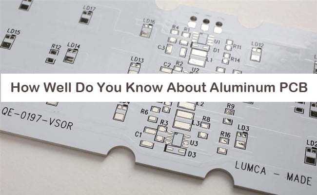
How Well Do You Know About Aluminum PCB

Introduction to Aluminum PCB Aluminum PCB is a Printed Circuit Board that contains a thin layer of conductive electrical insulator material. They are also known

rigid pcb guide
Will Li

Rigid PCB: Everything Beginners Need to Know is Here

Rigid PCB is the most common type of PCB, they provide sturdy mechanical support for mounted electronic components, while enabling efficient manufacturing using automated assembly processes.

Scroll to Top