Rigid vs. Flexible PCBs: Which One is Best?
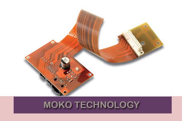
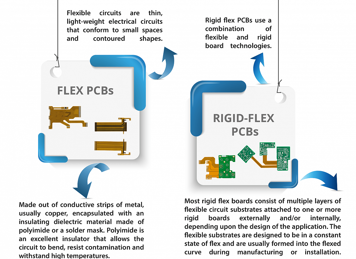
A rigid-flex printed circuit board (PO) is a half and half circuit board plan that incorporates components from both hardboard and flexible circuits. Rigid-flex PCBs are rigid at certain focuses on the board and flexible at others. Along these lines, rigid-flex PCB can be collapsed or consistently flexed while keeping up the state of territories that need additional support. The circuits are regularly multi-layered and are included flexible circuit substrates got together with rigid sheets. The flexible layers are covered entirely and inside infiltrate the rigid areas of the PCB.
One of the key advantages of a rigid-flex PCB is its thin profile. The standard dielectric in flexible circuits is .001 – .002″, settling on it an amazing decision for ultra-slight—and ultra-light—bundling needs. Adhesiveless overlays, HDI, and flimsy copper layers make it perfect for exceptional line innovation, giving you the Smallest, most lightweight, and lightest answer for your circuit plans.
Rigid-Flex PCB Types
Rigid-flex PCBs support two essential application types: flex to introduce and dynamic flex.
Flex to introduce is the most well-known kind of rigid-flex PCB application. In this circuit application, the board overlays just once when the gadget is amassed or evacuated. In actuality, the flex some portion of the board stays stable all through use, despite the fact that some development may happen on account of high vibration applications.
Thus, it is some of the time vital for a PCB to have the option to create and more than once twist during final result use. This kind of circuit application is known as a unique flex. It requires exceptional thought to guarantee the flexible portion of the board can withstand rehashed wear. At the point when planned with a proper twist sweep, these circuit sheets can be trusted to keep going for a huge number of flex cycles without issue.
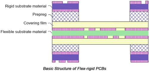
Rigid-flex PCB structure
The Feature Of Rigid Flex PCB
- All lines are arranged, which can spare the association work of overabundance line;
- Less weight and space prerequisite makes these rigid flex circuits a perfect decision for medicinal applications, for example, pacemakers.
- It can viably diminish the volume of the item, and more helpful to convey.
- It can lessen the heaviness of the firm item;
- It can improve the delicateness and reinforce the get together of the three-dimensional space in the constrained space.
Rigid-flex PCB Applications
While they come at a greater expense, rigid-flex sheets are unbelievably adaptable and can be tailored to applications over a wide scope of businesses. They are profoundly appropriate for military, aviation, and therapeutic gadgets, yet they can likewise be actualized towards certain business items. A few conditions make Rigid-Flex PCBs as an ideal arrangement. In such circumstances, these sheets are worth the venture, yet in addition, might be the most financially savvy decision. These include:
• High-stun and high-vibration situations. Rigid-flex PCBs are exceptionally stunned safe and can get by in high-stress situations that would some way or another cause gear disappointment.
• High-exactness applications where unwavering quality is more important than cost contemplations. In circumstances where a link or connector disappointment would be hazardous, the more strong rigid flex PCBs are ideal.
• High-thickness applications. A few congregations do not have the imperative surface zone for all the vital connectors and cables. A rigid flex circuit can streamline space to take care of this issue.
• Applications requiring different rigid sheets. At the point when congregations become busy with more than four associated sheets, it might be ideal and more practical to supplant them with a solitary rigid flex PCB.
Advantages
More extensively, rigid flex PCBs have the accompanying focal points:
• Endure significant levels of stun and vibration
• Endure countless flex cycles
• Decrease bundle weight
• Increment circuit thickness
• Lessening important gathering tasks.
Rigid flex circuit gatherings are perfect for lessening or potentially dispensing with connectors, just as the labor, yield, transmission, and unwavering quality gives that are inalienable in their application. Along these lines, any get together that can profit by these highlights can profit by a rigid flex PCB.
Commonly used material of flex-Rigid PCBs
The performance of rigid flex pcb relies upon that of substrate material of them that fundamentally contains flexible dielectric film and flexible glue film. As the main kind of flexible substrate material, flexible dielectric film, for the most part, incorporates polyester (Mylar) that is generally utilized in low-finished results, polyimide (Kapton) that is the commonest type, and fluoropolymer (PTFE) that is normally utilized in military and aviation items.
As those three kinds of flexible materials are looked at, polyimide highlights the most elevated dielectric steady with brilliant electrical and mechanical properties and high-temperature obstruction however is costly and simple to absorb dampness. Comparative with polyimide as far as performance, polyester, notwithstanding, includes awful high-temperature opposition. Polytetrafluoroethylene is essentially utilized in high-recurrence items with low dielectric constant.
The main material adding to flexible glue film contains acrylic corrosive, epoxy and polyester. Acrylic corrosive and polyesterimide include incredible attachment, high flexibility and generally high synthetic obstruction and warmth opposition. Notwithstanding, it includes a moderately enormous coefficient of warm extension so its inside thickness ought not to be over 0.05mm. Epoxy gum includes a terrible bond and is, for the most part, applied to stick covering layer and inward layer. Moreover, it highlights such a low coefficient of warm extension that it’s advantageous to warm stun opposition improvement of plated through gaps.
Flex Circuit Overlay
Flex circuit overlay, or coverlay, as it’s likewise known, is a cover procedure utilized for exemplifying and securing the outer hardware of a flex circuit. A flex circuit’s coverlay film is like a rigid PCB‘s weld veil, with one major difference, the coverlay film is flexible! According to allflexinc.com, “The coverlay film is by and large a polyimide film that is covered with a thermoset cement. Film thicknesses extend from .0005″ to .005″ with .001″ and .002″ the most well-known.”
When to Use Rigid & When to Use Flexible
Rigid flex PCBs ordinarily cost not as much as flex circuits. I state “normally” in light of the fact that when considering the complete expense of possession there are a few applications that, when utilizing flexible PCBs, might be more affordable contrasted with utilizing rigid PCBs. To get a genuine and precise comprehension of the complete expense of proprietorship, you first need to welcome the way that flex circuits may take out the requirement for parts, for example, connectors, wire outfits, and other Numerous electronic gadgets (PC and personal computers, sound consoles, strong state drives (SSDs), level screen TVs and monitors, kids’ toys and different electronic devices) utilize rigid PCBs rather than flexible PCBs. Furthermore, flex circuits might be found in ultra-conservative or potentially elite gadgets, including GPS units, tablets, PDAs, cameras, and wearables.
More noteworthy modernity isn’t the main motivation to utilize flex circuits; low-tech applications may use flex circuit innovation now and again in light of the fact that it makes the establishment a lot simpler.
Understanding when to utilize both
Presently you need to comprehend when to utilize a rigid PCB and when to adhere to a flexible PCB. Obviously, the rigid ones cost not as much as flex circuits. On the other hand, the expense of proprietorship and the application can decide the amount you need to spend. There are occurrences where the utilization of flex circuits can diminish the costs you cause. On the off chance that you might wish to comprehend the all-out cost of proprietorship, at that point you should recognize a couple of actualities. Flex circuits dispose of the requirement for a few segments like connectors, wire tackles, and other circuit sheets. In the event that you address flexible circuit board producers, at that point they will say something very similar.
Certainly, a flex circuit and a rigid flex PO can be utilized together—as a brought together PCB—if the need emerges. This methodology, maybe, gives the best of the two worlds.
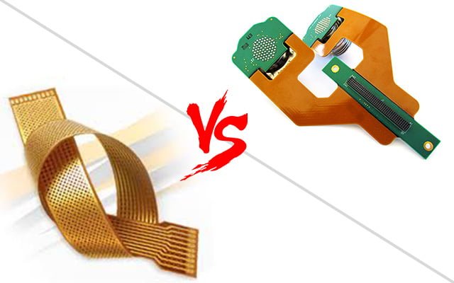
The Differences
When planning rigid PCBs, certain structure rules must be pursued, including least gap sizes, least space and follow width, least separations to board edges, and copper and in general structure thicknesses. Also, many assembling procedure steps are shared among rigid and flexible PCBs. Such procedure steps incorporate the penetrating and plating of gaps and vias, photograph imaging and advancement, the drawing of copper follows, cushions, layouts, and planes, and the warming (heating) of the circuit loads up for the motivation behind expelling dampness from the PCBs. Now in the assembling procedure, rigid PCBs head to the weld veil station while flex circuits go to the coverlay station.
| Rigid | Flexible | |
| Definition | A rigid-flex circuit is a half breed development of the FPC board and FR4 board, it is covered together into solitary structures. That is, both rigid and the flex parts are planned with follows and they are associated, the FR4 doesn’t act just as a stiffener, there would be circuit both on FPC and FR4 board. | FPC (Flexible printed circuit) alludes to a slight protecting polymer film having conductive circuit examples appended. The most preferred position for FPC is flexibility, which enables it to be great association inside a conservative space or parts that need to bow. |
| Production & Price | While rigid-flex PO is similarly mind-boggling, they need an overlay of the FPC circuit and FR4 load up ordinarily when manufacturing rigid-flex PCBs, the factory needs both rigid PCB generation machines and flex PO creation machines, with more than 50 procedures, the quality control will be more troublesome. On account of the generation trouble, the rigid-flex PO is normally significantly more costly than some other sheets, for example, FR4/FPC with stiffener,they are typically just utilized in quality requests activities, for example, military tasks, satellite. | It’s basic for the generation procedure of rigidized flex development, the factory will bond stiffeners after the FPC delivered. As the modest value, the FPC is generally utilized and the expense is moderately low. FPC is more typically utilized on customer electronic items, for example, cell phones, workstations. |
| Material | It contains flexible dielectric film and flexible cement film. | The flexible film, for the most part, incorporates polyester (Mylar) that is typically utilized in low-final results, polyimide (Kapton) which is the commonest type, and the fluoropolymer (PTFE). |
What are the means to make a rigid-flex PCB
- Manufacturing rigid-flex structures are more mind-boggling than making a basic rigid plan since 3D space is required so as to build up a rigid flex structure.
- The base material of a rigid portion is made out of FR4 and the flex portion is comprised of polyimide and after that copper foil and coverlay holding film are applied.
- In the initial step of assembling rigid flex PCB, accessible glues are applied on a copper layer.
- After that slender layer of copper foil is covered on the glues. Copper plating can likewise be utilized instead of overlay process.
- The next step includes the boring of little gap on the flex substrate. Laser penetrating is most appropriate for making exact and precise openings.
- Copper is stored into the gaps when they are penetrated into the flex design. This procedure is known as the through opening plating in which copper is synthetically plated.
- In the subsequent stage, Photosensitive engraving opposes covering is applied on the flex surface. The window ornament coat technique is perfect for this procedure.
- The copper film is appropriately carved once the covering is applied. From that point forward, draw oppose is expelled from the circuit board.
- In the subsequent stage, coverlay insurance is applied on the top and base layers of the flex substrate. Polyimide material is a perfect decision for utilizing as a coverlay security.
- Blanking is a subsequent stage in which flex substrate is cut dependent on the plan necessities. Kick the bucket set and Hydraulic punch are the most ordinarily utilized procedures for cutting the flex. These techniques include the cutting of different flex with high exactness and precision.
- In the last advance, a flex board, produced using the blanking procedure, is overlaid between the rigid layers which result in the last item that can be electrically tried to make it accessible for the electronic reason.
Rigid Flex PCB Cost
The essential purpose behind the more costly PCB tooling charges related to flex or rigid-flex circuit sheets truly comes down to the measure of physically made building programs a particular structure may have. The other explanation is the volume; however underway volumes we commonly observe that most clients recover the extra cost in 2000 pieces or less.
The other factor in the expense of tooling pursues comes to volume. For rigid-flex and additionally flex models and little volume runs, most are made with laser cutting or some kind of mechanical directing. This is utilized to make the surface mount includes in the coverlays, part diagram, and whenever required, the framework of the stiffeners.
Electrical testing on these lower volumes is ordinarily finished with a flying test. In volume creation of flex and rigid-flex circuits, you have to switch over to steel rule passes on or male/female punch and bite the dust sets. This steel rule kicks the bucket and is regularly more costly to make refrains the laser cutting system. The electrical test apparatuses are likewise exchanged over to a hard-wired test, which can be more labor serious. Both of these factors can include an underlying forthright cost, yet it considers a generous decrease to the unit cost of the part when you are managing higher volumes.
- Layers are the most important factor, if single-sided flex is sufficient, never attempt more layer
- Flex Board types: Single Pieces or in Panel, when doing Flex PCB Cost Estimator, consider material use rate, flex PC material is move unit, one of side can’t be more then 250mm, when creation, we will set working board size, if waste parcels, this will ascertain into flex PCB cost .
- Min Track/Spacing, 2-3mil.
- Min Hole Size, not be excessively little, 0.25.
- Gold Fingers, two choices for flex PCB gold finger, hard gold or inundation gold, hard gold is significantly more costly.
- Copper Thickness: 1/3 oz is normal, keep flexible, not propose overwhelming copper.
- Stiffener, Flex PO connector has 3 choices to choose stiffener: Fr4 stiffener, Aluminum stiffener, Pi stiffener, in the event that you Plug recurrence, recommend utilize harder stiffener.
- Surface Finish: Normal is drenching gold.
- Size: more material utili7ntion rate, more less expensive.
- Quantity: The more the less expensive
In Conclusion
Despite the fact that both rigid and flexible printed circuit sheets on a very basic level fill a similar need—connecting different electrical and mechanical segments together—the two innovations have their place throughout everyday life. While a significant number of similar plan rules are utilized with both rigid and flexible PCBs, flexible PCBs require some extra rules because of their extra assembling procedure steps. Furthermore, despite the fact that rigid PCBs may appear, in any event at first, to cost less, one should consider a plan’s all out the cost of proprietorship before announcing that flex circuits are excessively costly.
Everything thought of it as’, important to take note of that not all board houses are fit for assembling flexible PCBs. Prior to beginning a flex circuit plan, you should meet various board houses and talk about flexible PO manufacture choices and related costs.