Home » Rigid PCB
Rigid PCB
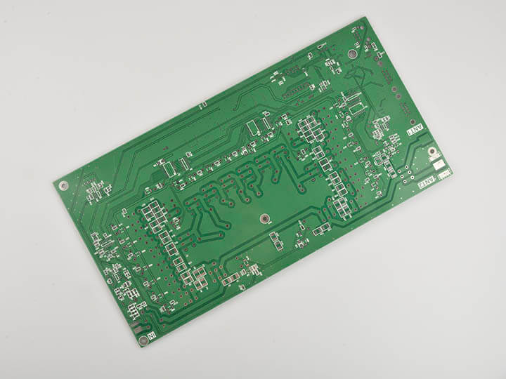
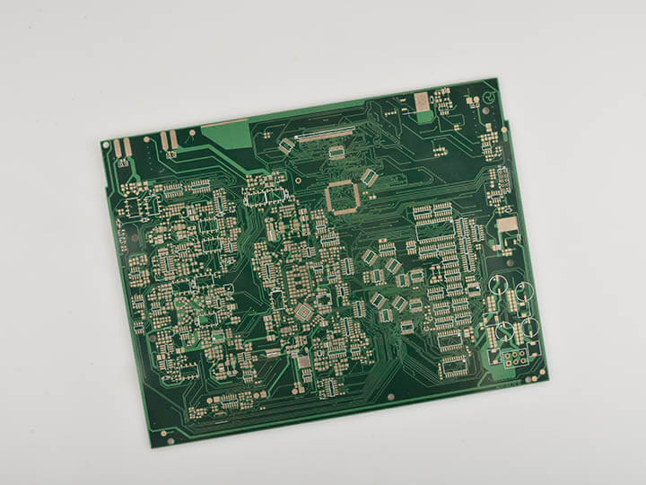
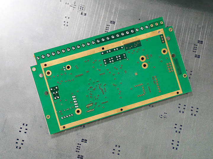
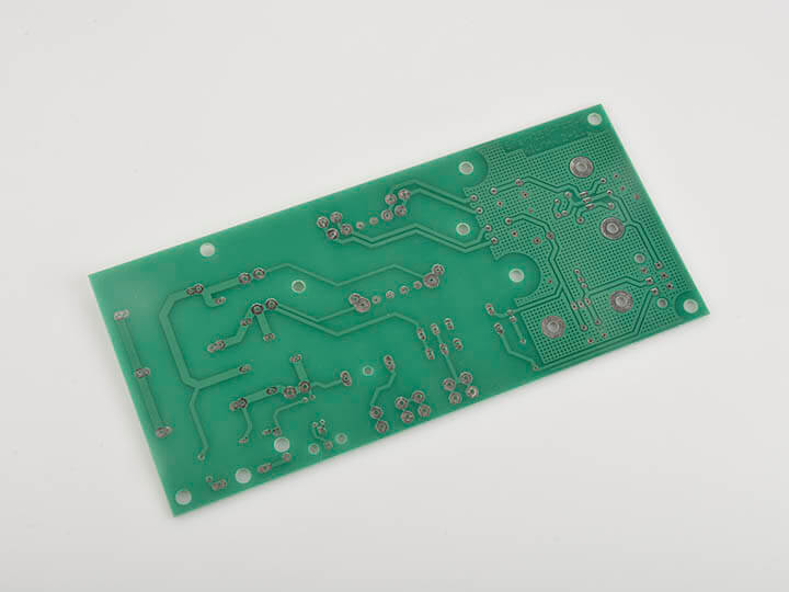
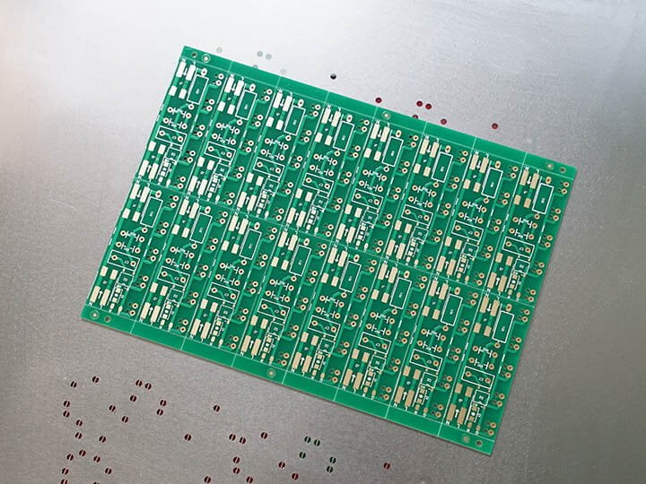
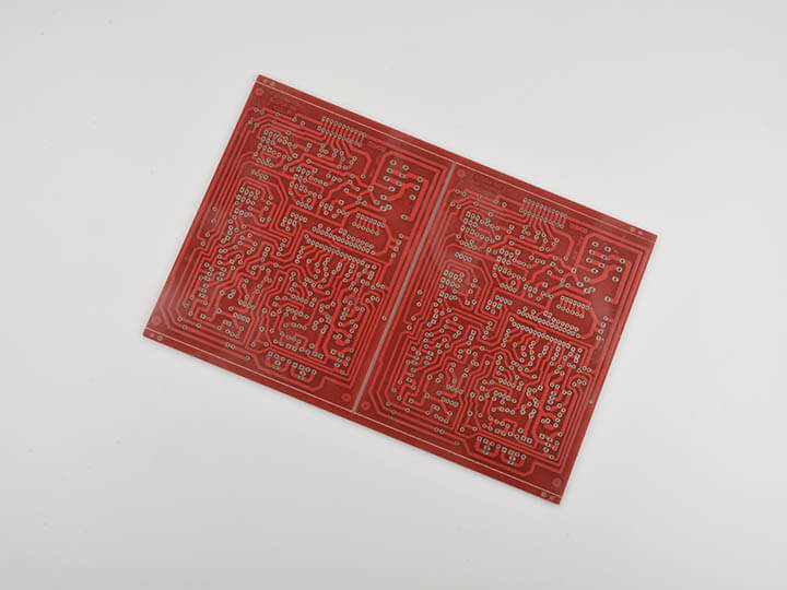
We get to see the wonders of technology every day from airplanes to telecommunication equipment. All of these amazing things are only possible thanks to the manufacturing of rigid PCB. If you are ever using a laptop and wonder how it works then you should know that its important modules are relying on rigid PCB. That electronic dashboard in your car and that flashy smartphone you use are all thanks to the rigid PCB. With these many applications, it is safe to assume that it is very difficult to manufacture a rigid PCB. If you delve further in this article then you will figure out exactly how to manufacture a rigid PCB.
MOKO Technology: A reliable Rigid PCB Manufacturer
When it comes to PCB manufacturing then MOKO Technology is a world leader and pioneer. Our PCB boards are of the highest quality and are very durable. So, our PCB offerings include Rigid PCB, Multilayer Flex PCB, and Rigid-Flex PCB. We have a very advanced technological setup that allows us to ensure customer satisfaction. Additionally, we have a dedicated R&D staff and our customer support is always available. So, if you decide to work with us then you will have access to our valuable resources. Hence, you can manufacture electronic products by incurring minimum costs and saving a lot of valuable time.
As a rigid PCB supplier, we can help you with the following:
1) Project Evaluation
Our experienced engineers will extensively review and analyze your requirements. Afterward, we will help you with component selection, cost reduction, and feasibility reporting.
2) Development of Hardware
We have years of experience in developing complex hardware. So, our team will diligently develop the hardware and firmware that you need.
3) Industrial Design
Our team will come up with a pragmatic design for your product architecture. So, for this purpose, we will leverage our superior CAD technology.
4) Testing
Relevant testing is empirical when it comes to rigid PCB. So, we offer in-house testing and inspection services for all of our products.
5) Certification
We comply with international standards and we have relevant industrial certifications. So, as per your needs, we can readily offer RoHS, CE, and FCC certifications.
Rigid PCB Manufacturing process
1) Material Preparation
We start with only bare bone boards. Then we clean them by applying chemicals. So, after that, we apply photo resistive films on them. This is because we want to make sure that the boards don’t incur damage of any sort.
2) Exposure of Circuit Pattern
We then lay down the respective circuit patterns on the board. So, we perform this process by applying UV rays on the board. This allows us to ensure that the circuit images transfer onto the board.
3) Etching
Then we perform etching to ensure that the circuit patterns permanently stay on the PCB board. For this purpose, we use automatic handling machines and special chemical etching equipment.
4) Drilling
Then we start drilling holes over the circuit patterns. We must ensure that the holes have a certain size as per the standard specifications.
5) Copper Plating
Then we initiate the process of copper plating. So, in this process, we apply copper onto the board. Hence, it allows us to create electrical connections in multiple layers.
6) Coverlay Application
We then apply coverlay laminate over the PCB. This allows us to protect the PCB and enhance its performance. So, we can perform this process both manually as well as automatically.
7) Stiffener Application
Stiffeners act as supportive elements and we use them for preventing distorting and loosening. So, we have to use heat or pressure for the successful application of stiffeners.
8) Mounting
The final step involves assembling the PCB. So, we often use PTH (Plated Through Hole) technology for mounting Rigid PCB design. This step involves the application of lead through the drilled holes. We then solder the lead to the pads on the opposing side of the PCB.
Advantages and disadvantages of Rigid PCB board
Advantages
- These are compact and lightweight. Hence, it is much easier to pack them.
- They are more reliable and durable when dealing with high-end applications.
- These have superior thermal stability. Therefore, these boards are more preferable for aerospace and nuclear applications.
- They show good resistance to chemicals, radiations, and aggressive oils. Hence, we can readily use them in hostile environments.
- We can design them in such a way that they mount from both sides.
- They have a wide range of options available for material selection. Hence, it is very easy to meet customer requirements.
- We can enhance their properties to withstand vibrations, stresses, and shocks. Hence, they are ideal for industrial applications.
Disadvantages
- The manufacturing process is very difficult. Hence, small firms can often face significant problems.
- The manufacturing requires a sophisticated setup. Hence, significant capital is needed.
- We need skilled and experienced workers for material handling.
- Rigid PCB thickness often tends to show brittleness which can lead to system failure under certain conditions.
Repair and reflow are extremely difficult and is not practical in most cases.
When to Use Rigid circuit boards and When to Use Flexible PCB
Both have their pros and cons and both have unique properties. Hence, they are both suitable for different applications. However, their relevance and use depend on your unique needs and requirements. So, we can only give you a general guideline for your reference. If you are working with high-end applications that are subject to extreme conditions then you should go with Rigid circuit boards. However, if you are working with mid-tier applications with mild conditions then you should go with Flexible PCB.
Rigid PCB Application
1) Industrial Automation and Electronics
We can use a rigid board for supporting hardcore industrial applications. So, we can use a multilayer PCB to create buried connections and providing controlled impedance. Additionally, we can use them in applications that involve high frequency, high power, and high voltage. Some prominent examples include automation in robotic arms, conveyor belts, pressure controllers, gas tank monitors, and temperature controllers.
2) Medical Applications
We can also use them in a wide range of medical applications. However, they have restricted use in this sector as we only use them in large equipment. Some prominent examples include EMG (electromyography) equipment, tomography machines, and MRI systems.
3) Aerospace Applications
The aerospace sector is known for its extreme environment and conditions. Some of the major challenges include high temperature, friction, and high pressure. So, in this case, rigid circuit boards are very beneficial. This is because we can design them with premium substrates and superior laminates. Some prominent examples include cockpit equipment, temperature sensors, control mechanisms, routing equipment, dashboard instrumentation, black box equipment, etc.
4) Automotive Applications
We can see an intensive use of rigid circuit boards in automobiles. We have to deal with extreme conditions when it comes to vehicles. So, we tend to rely on rigid circuit boards because they have lamination. This lamination can protect them from the high amount of heat generated by the engine. Additionally, we can also use a rigid printed circuit board in the dashboard of the vehicle and as an AC/DC power converter. They are also very useful as transmission units, junction boxes, electronic computer units, and power distributors.
Material Selection for Rigid circuit boards
Substrate Layer
- We mostly use fiberglass for making the substrate layer.
- However, we also extensively use FR4 for making the substrate. This imparts stiffness and rigidness to the PCB board.
- Additionally, we also use epoxies and phenolics as substrates. Although they are more economical they are inferior to FR4 and have a bad odor.
- Phenolics degrade at even low temperatures. So if you place the solder for too long then it may result in delamination.
Copper Layer
- We place a copper foil on top of the base material. This acts as a lamination on the board. So, we have to use adhesives and extra heat for placing them.
- Usually, both sides of a PCB board have a copper lamination. However, we may compromise on only one layer of lamination in case of cheap products.
- The thickness of the copper lamination varies for each board as per the requirements and needs.
Solder Mask Layer
- We place a solder mask over the copper lamination.
- We add this layer to ensure that there is more insulation. Hence, we can provide better protection from any sort of damage.
Silkscreen Layer
- In most cases, we also place a layer of silkscreen on top of the solder mask.
- We do this so that we can impart any symbols or characters on the PCB board. This helps users to better understand the board.
We mostly utilize white color for silkscreens. But other colors such as red, yellow, black and grey are also available.
Main Specifications of rigid circuit boards Manufacturing
While manufacturing rigid circuit boards the most important thing is to ensure that the thermal coefficients of the substrates and the laminates are consistent with each other. Apart from that, some other prominent specifications are as follows:
| Layer | 1-50 layer |
| Material | FR-4, CEM-1, Hight TG, FR4 Halogen Free, FR-1, FR-2, Aluminum |
| Board Thickness | 0.2-7 mm |
| Max.finished board side | 500*500 mm |
| Min.drilled hole size | 0.25 mm |
| Min.line width | 0.075 mm(3mil) |
| Min.line spaceing | 0.075 mm (3mil) |
| Surface finish/treatment | HALS/HALS lead free, Chemical tin, Chemical Gold, Immersion gold Immersion Slive/Gold, Osp, Gold Plating |
| Copper Thickness | 0.5-4.0 oz |
| Solder mask color | green/black/white/red/blue/yellow |
| Hole Tolerance | PTH: ±0.076, NTPH: ±0.05 |
