Is there a reason an 0805 resistor would have a different land pattern than an 0805 capacitor?

My PCB design software comes with some libraries that include some common components, like chip resistors and capacitors. I have noticed, however, that the footprint land pattern for the 0805 resistor is not identical to the 0805 capacitor.  Is there a "best standard"? IPC-7351, IPC-SM-782, or what?

The current standard is IPC-7351B, which replaced IPC-7351A, IPC-7351, and IPC-SM-782 (in that order).

Mentor Graphics has a free PCB land pattern viewer for Windows (old link; they rebranded to PADS) for all of the standard parts using this standard. Each part also includes a “courtyard” layer which defines how much space needs to be left around the component for manufacturing. It is useful when you are designing high-density boards.

The standard itself consists of three versions, but for most boards, it is recommended that the “N” suffix (Nominal) footprints are used. Note that most parts do differ slightly from manufacturer recommended patterns, but in my experience (and the experiences of my board loader) these footprints do tend to meet manufacturing requirements very well.

As for you query about the 0805 resistor versus the 0805 capacitor, I suspect that the footprints have been designed to best attach the parts. While they are fairly similar in the horizontal plane, capacitors tend to be slightly higher. Thus, maybe the differences in the footprints take this into account.

Read More: PCB Assembly

#PCB Assembly #PCB Design
Picture of Oliver Smith

Oliver Smith

Oliver is an experienced electronics engineer skilled in PCB design, analog circuits, embedded systems, and prototyping. His deep knowledge spans schematic capture, firmware coding, simulation, layout, testing, and troubleshooting. Oliver excels at taking projects from concept to mass production using his electrical design talents and mechanical aptitude.

What Others Are Asking

How can I mount a pulse oximeter on the surface of PCB without putting too much stress?

The PCB has a pulse oximeter mounted on the surface, and it’s tolerance is 0.6mm. The problem is the pulse oximeter needs to touch the bottom case at all times. How to best mount the PCB in the case without putting too much stress on the pulse oximeter? Will screws with flexible washers be all right? Sadly separating pulse oximeter from main PCB is not an option.

Where should I store PCB?

I have received the final prototypes from manufacturer and all is good after our checking. And we want to keep it well. Do you have any tips about that?

Read Detailed Advice From Blog Articles

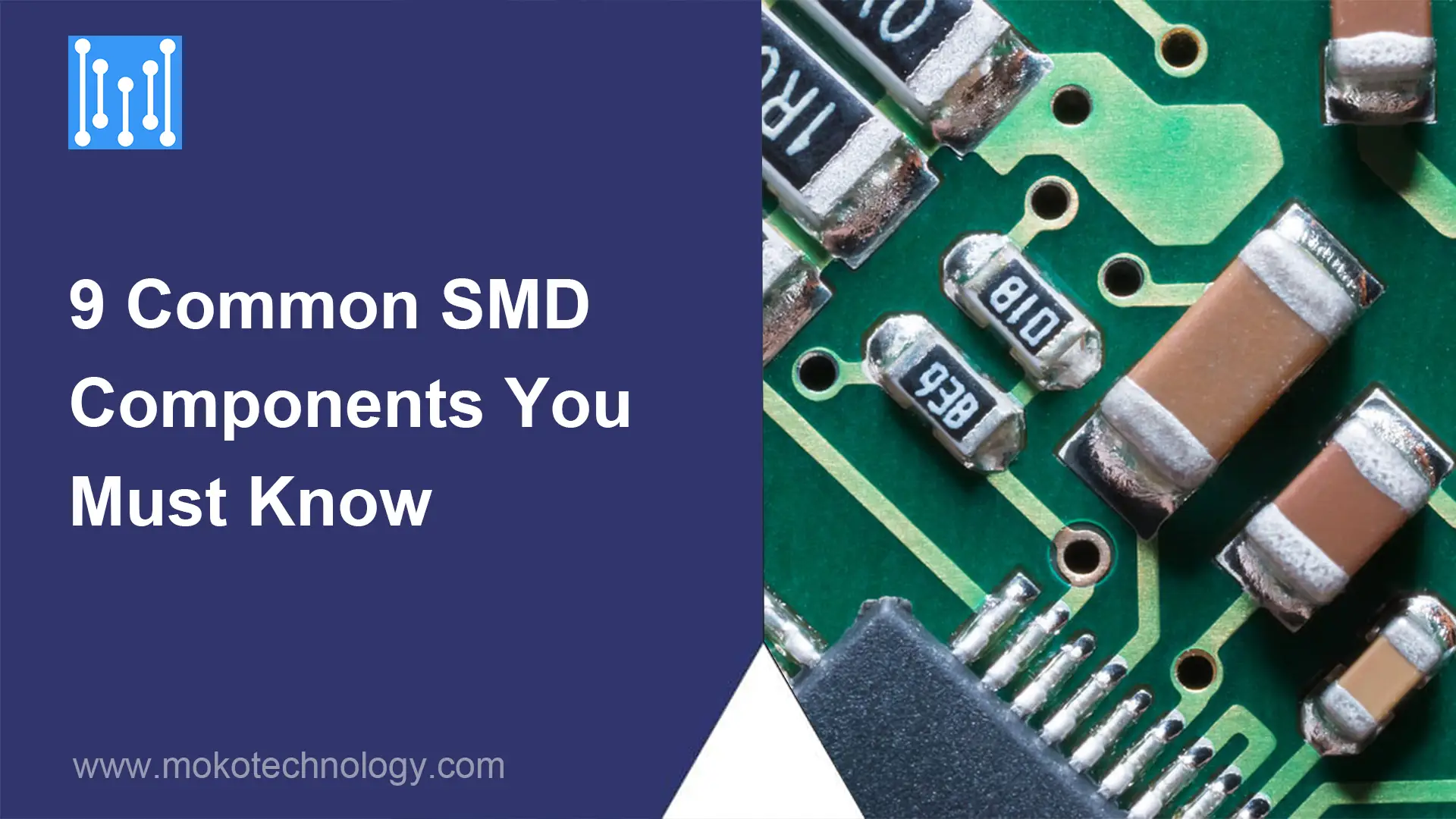
9 Common SMD Components You Must Know
Will Li

9 Common SMD Components You Must Know

I’ve always been fascinated by the tiny electronic components that power our modern devices. As I’ve learned more about electronics, I discovered the world of

Introduction to SMT PCB Assembly
Will Li

Introduction to SMT PCB Assembly

SMT PCB assembly has become the most popular PCB assembly technology since the 1980s, and is now widely used in industries such as consumer electronics,

Scroll to Top