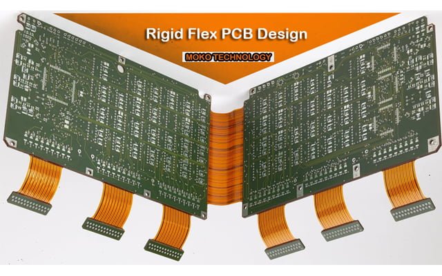
Rigid Flex PCB Design: Benefits and Design Best Practices
With the use of a rigid flex PCB(rigid FPC), flexible circuit substrates and rigid circuit substrates are covered together. Rigid-flex PCBs cross the limits of conventional rigid PCBs and the one of a kind properties of flex circuits that utilization high-flexibility electrodeposited or moved strengthened copper conductors photograph carved onto a flexible protecting film.
Flex circuits incorporate stack-ups produced using a flexible polyimide, for example, Kapton or Norton and copper-covered together through warmth, acrylic cement, and weight.
Likewise, with customary PCBs, you can mount segments on the two sides of the rigid board. As a result of the mix that happens among rigid and flex circuits, a rigid-flex configuration doesn’t utilize connectors or connecting cables between the segments. Rather, the flex circuits electrically interface the framework together.
The absence of connectors and connecting cables achieves a few things:
- Improves the capacity of the circuit to transmit signals without misfortune
- Accommodates controlled impedance
- Eliminates association issues, for example, cool joints
- Reduces weight
- Frees space for different parts
Each rigid-flex PCB is separated into zones that element various materials and differing layer tallies. Rigid zones sometimes have more layers than flexible zones, and materials move from FR-4 to polyimide experiencing significant change zones.
Complex structures frequently change from rigid to flex and back to rigid on different occasions. As these convergences happen, the cover of rigid-flex materials requires repelling openings from the change zone to look after honesty. Likewise, numerous rigid-flex plans incorporate hardened steel or aluminum stiffeners that give extra support to connectors and segments.
Rigid FPC loads up cost a lot more than practically identical hardboards and are typically a few times the expense of a flexible circuit with stiffener.
Nonetheless, the expanded expense is legitimized with regards to explicit applications and situations, for example:
- High-unwavering quality applications. In the event that a get together will be presented to inordinate or rehashed stun, or high vibration situations, connectors with flexible cables are more prone to fall flat. Rigid FPC gives incredible dependability in any event when exposed to extraordinary vibration and stun applications.
- High-thickness applications. Inside a little fenced in area, it’s occasionally difficult to oblige every one of the cables and connectors that an electronic PCB configuration would require. Rigid FPC sheets can overlay into very little profiles, offering significant space investment funds on these occasions.
- Five or more rigid sheets. In the event that your application will at last include five or more rigid sheets associated with each other with flex cables, a coordinated rigid flex arrangement is regularly the ideal and more financially savvy decision.
Diverse Design Rules Apply to Rigid-Flex PO Design
Various difficulties counterbalance the adaptability and flexibility that enable you to manufacture three-dimensional plans and items. Conventional rigid-flex PO plans enabled you to mount segments, connectors, and the frame for your item to the physically more grounded rigid piece of the get-together. Once more, as far as customary plans, the flexible circuit just filled in as an interconnect while bringing down the mass and improving the protection from vibration.
New item structures combined with improved flex circuit innovations have presented new plan rules for rigid-flex POs. Your structure group presently has the opportunity to put parts on the flexible circuit territory. Consolidating this opportunity with a multilayer way to deal with rigid-flex configuration enables you and your group to incorporate more hardware with the structure. In any case, picking up this opportunity includes a couple of difficulties as far as directing and gaps.
Flexible circuits consistently have twist lines that influence steering. On account of the potential for material pressure, you can’t put parts or vias near the twist line. Also, in any event, when segments are appropriately found, bowing flex circuits spots rehashed mechanical weights on surface-mount cushions and through openings. Your group can lessen those worries by utilizing through-opening plating and by reinforcing cushion support with extra .overlay to anchor the cushions.
As you plan your follow steering, pursue rehearses that lessen the weight on your circuits. Utilize incubated polygons to keep up flexibility when conveying a power or ground plane on your flex circuit. You should utilize bent follows instead of 90° or 45° edges and use tear examples to change follow widths. These practices reductions emphasize focus and shaky areas. Another best practice conveys worry crosswise over follows by amazing the top and base follows for twofold sided flex circuits. Balancing the follows keeps the follows from laying over one another a similar way and reinforces the PO.
You ought to likewise course follows opposite to the twist line to lessen pressure. When replacing rigid with flex and flex with rigid, the quantity of layers from one medium to the next may vary. You can utilize follow directing to add solidness to the flex circuit by balancing the steering for nearby layers.
Rigid FPC Design Guidelines
Extensively, a rigid flex configuration will intently look like a hardboard structure, with the flexible layers completely stretching out into the rigid regions of the board. So also to hardboard formats, a rigid flex creation bundle will incorporate Gerber layers, alongside drill documents, patch veil layers, classification, perimeter route records, a cover layer, and so on.
Ordinarily, there are some key contrasts between the manufacture bundles for rigid FPC’s and hardboard applications:
- A rigid FPC, by and large, has a lot more measurements on it, and ought to deliberately characterize the necessities, as these sheets are commonly utilized in 3D applications. It ought to likewise precisely characterize the rigid to flex progress zones, as these are not constantly clear when surveying the Gerber layers alone.
- The material layup in rigid flex sheets is basic, and ought to be worked out in collaboration with your fabricator. Your fabricator can assist you with settling on the correct decisions in materials based on your necessities, for example, UL combustibility rating, least twist radii required, mechanical contemplations, impedance control on both flex and rigid layers, RoHS affirmation, lead-free get together similarity, and different contemplations.
- Rigid flex sheets, as a rule, require extra layers in the Gerber documents. Layers 1 and X will have weld veil layers, yet you will likewise require artwork layers that characterize the cover layer and bondply segments (whenever expected) of the board, and how much each go into the hardboards. IPC 2223 suggests 0.100″ however your fabricator might have the option to oblige not as much as that.
What affects the design of rigid-flex PCB
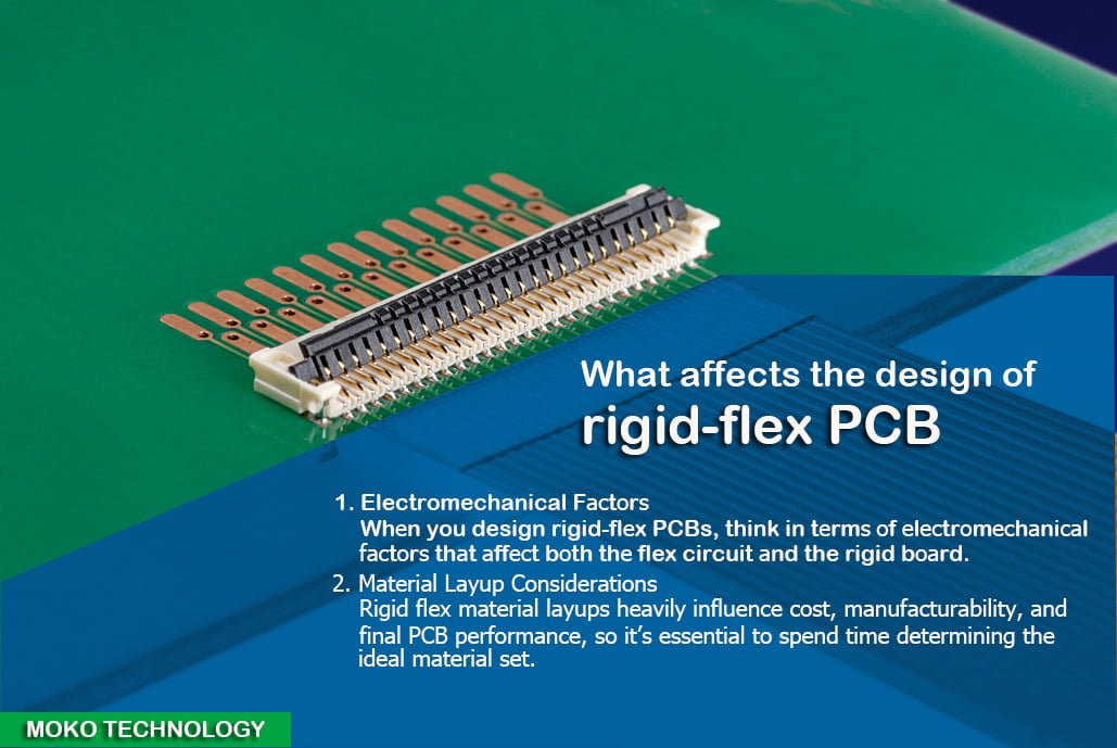
Electromechanical Factors Influence Design
At the point when you plan rigid-flex PCBs, think as far as electromechanical factors that influence the flex circuit and the rigid board. As you construct your structure, center around the proportion of curve range to thickness. With flex circuits, tight curves or an expanded thickness at the twist region increment the odds for disappointment. Fabricators suggest keeping the curve span at least multiple times the thickness of the flex-circuit material and building a “paper doll” of the same circuit to figure out where twists happen.
You ought to abstain from extending the flex circuit along with its external twist or packing it along with the inward twist. Expanding the curve edge past 90° builds extending at one point and pressure at another point on the flex circuit.
Another key issue in rigid-flex unwavering quality is the thickness and kind of conductor found in the twist locale. You can diminish thickness and mechanical worry by lessening the measure of plating on the conductors and utilizing cushions just plating. The utilization of substantial copper, gold, or nickel plating diminishes flexibility at the curve and permits merlinnical stress and cracking to happen.
Material Lay-up Considerations
Rigid FPC material layups intensely impact cost, manufacturability, and last PCB performance, so it’s fundamental to invest energy deciding the perfect material set. For example, controlled impedance, opposition, and current-conveying necessities are terrifically important contemplations that influence both copper loads and material choice.
A PCB architect ought to collaborate with their board fabricator to examine these factors, so the subsequent plan agrees to all flag honesty necessities. When the creator has performed starting computations, the fabricator can check them, and give a more precise displaying of the impedance qualities of the board, and material set required to accomplish those qualities.
On the off chance that impedance attributes are not excessively basic, our you are searching for the least cost, most stable rigid-flex plan proposals. Rigid-Flex program offers the most reduced generally speaking material expenses for rigid-flex plan, while additionally giving a sheltered beginning stage for planners who are new to the rigid-flex structure.
In the event that you may want to get a snappy gauge on how much your rigid-flex configuration may co* attempt our Rigid-Flex Cost Estimator. The rigid-flex cost estimator will take your necessities and will give you an expected expense for low-level generation amounts. It is an incredible beginning stage to check whether your plan is monetarily attainable with your program prerequisites.
The rigid segments of rigid-flex sheets are generally 20 layers or less. There are times when they have more, yet generally, more than twenty layers are really uncommon. The hardboard areas don’t all must have a similar layer tally. For instance, you could have one rigid segment with 16 layers of hardware and one with 12. For any amount of time that the material layup is comparative for each and the loads up have a similar generally thickness, there will be no assembling issues. Every so often, a configuration may utilize hardboards that contrast in thickness, however, such setups are significantly more hard to make and different choices ought to be considered.
The flexible areas of rigid-flex sheets are typically one (singlet), two (doublet), three (triplet) or four layers (quad development). There are times when an originator needs more than four layers over the flexible areas of the load up, yet are quite often unbonded. Reinforced flex areas that have more than four layers can be very impervious to twisting as well as flexing. Copper loads on the flexible layers of the rigid-flex sheets are most regularly half and one-ounce loads.
Once in a while the electrical interest requires two-ounce loads. In those cases, the fashioner should work intimately with their fabricator to pick the correct no stream prepreg, to satisfactorily fill the thicker circuits in the hardboards. No stream prepreg, by configuration, doesn’t prefer to stream and two-ounce hardware can exhibit a few difficulties. Three-ounce copper weight is once in a while utilized and can show considerable issues in assembling for a similar explanation.
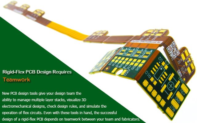
Rigid-Flex PCB Design Requires Teamwork
New PCB configuration instruments enable your plan group to deal with different layer stacks, visualizing 3D electromechanical structures, check configuration controls, and reenact the activity of flex circuits. Indeed, even with these apparatuses close by, the effective structure of a rigid-flex PCB relies upon teamwork between your group and fabricators.
Teamwork must start at the most punctual phases of the undertaking and proceed all through the structure procedure and relies on steady correspondence.
Moko Technology rest you assured with strong capacities and expertise, if you’re in need of rigid FPC, welcome to visit https://www.mokotechnology.com/