How can I handle missing solder mask opening on PCB footprint?

I have three through-hole PCBs that are missing front and back solder mask openings for two of the components. The solder mask (usually green) is covering the front and back solder pads. All other pads for all other parts are exposed. Is there a good way to remove the solder mask so that I can solder the components to the board?

You can use a burnishing pen, scratch brush, or fiberglass pen. It looks like an eraser pen but has fiberglass brush bristles come out. It’s much more precise, gentle, and safe than a knife, dremel, or sandpaper. Just pretend it’s an eraser. Normally used to scrape away oxidiation and rust.

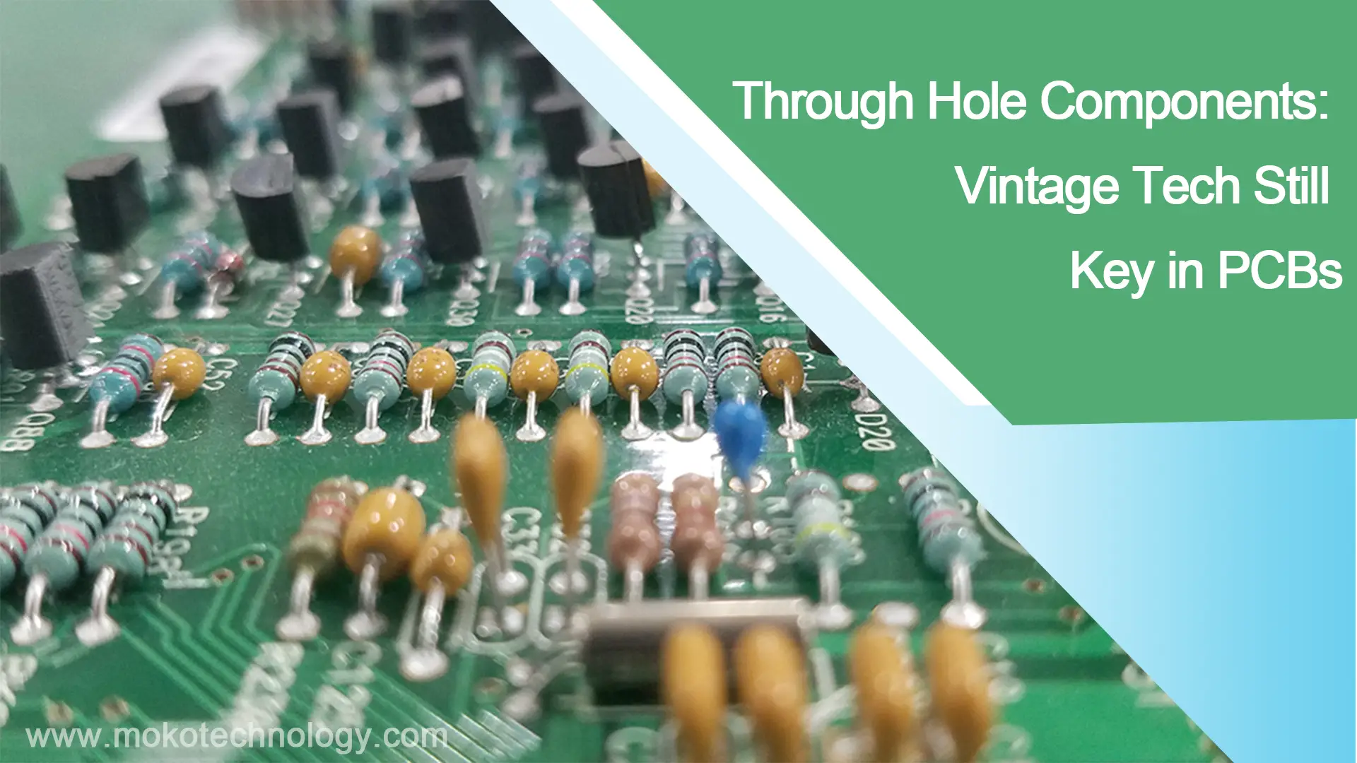
Read More: Through Hole PCB Assembly

#PCB Assembly

Picture of Oliver Smith

Oliver Smith

Oliver is an experienced electronics engineer skilled in PCB design, analog circuits, embedded systems, and prototyping. His deep knowledge spans schematic capture, firmware coding, simulation, layout, testing, and troubleshooting. Oliver excels at taking projects from concept to mass production using his electrical design talents and mechanical aptitude.

What Others Are Asking

Is aluminium foil a good substitute for kapon tape when soldering?

I want to desolder a tiny surface mount button from the motherboard of a phone. There are a lot of similarly tiny components surrounding it that I do not want to damage with heat from the soldering iron. Can I use aluminium foil in lieu of kapton tape to protect these components?

How to handle feedline of bluetooth PCB connected to a 2.4GHz chip antenna?

I’m making a 4 layer PCB prototype that uses a bluetooth mcu connected to a 2.4GHz chip antenna. I’m thinking about what to do with the feedline, whether it should be buried on one of the middle layers, or left on the top layer. To get a 50 ohm line, should I choose top layer with 13-mil width or buried miccrostrip with 7-mild width?

Read Detailed Advice From Blog Articles

Scroll to Top