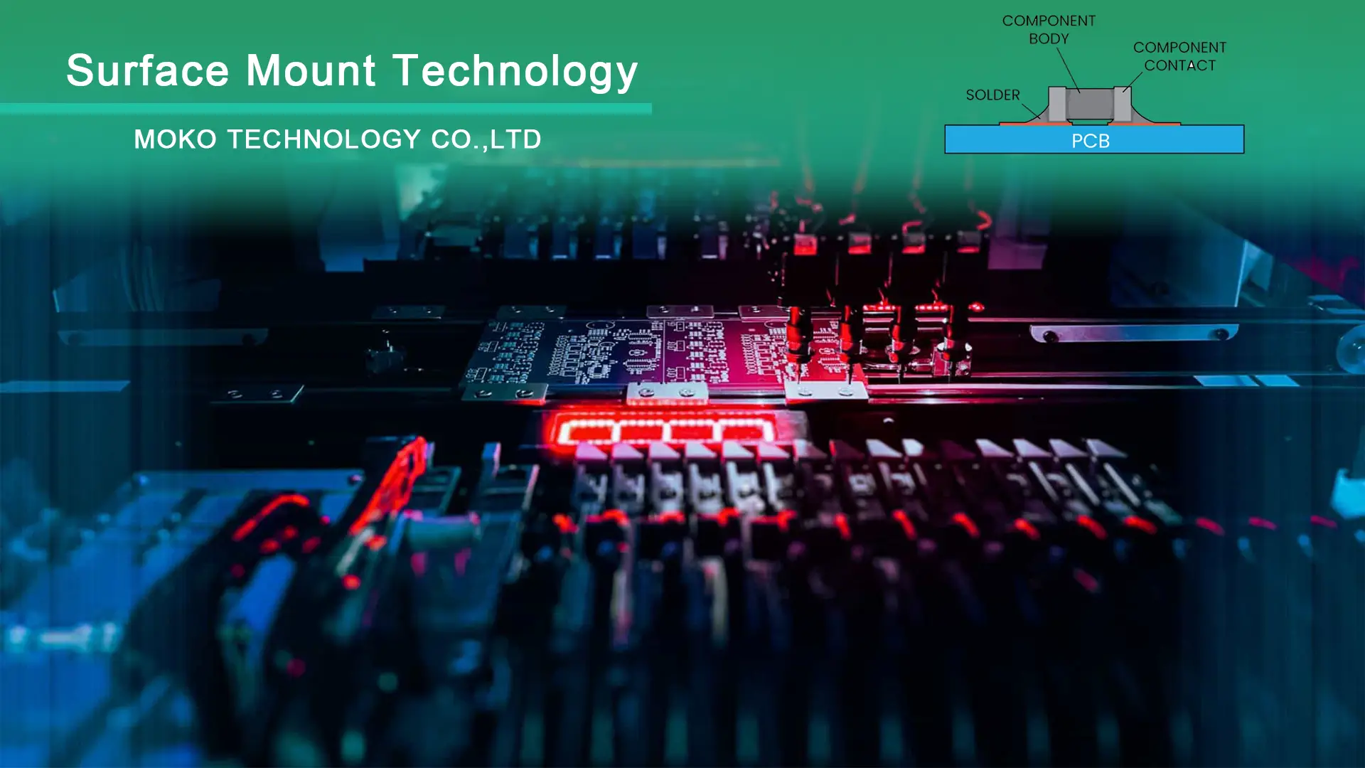
Do you use SMT or THT for USB mini B connector?

This question is about the advisability of continuing to use a USB mini-B right angle surface mount connector in my pcb designs. On occasion we see one of these connectors peel back or delaminate off the pcb. Immediately the question is asked, why didn't you use a through hole connector?

Use SMT.

I have experienced such a problem with the SMT Mini USB B connector in the past. Usually, the solution is to design the enclosure so that it will not allow any movement of the connector against the PCB.

As for the reason why to use SMT, SMT components are cheaper to assemble in large quantities. As a result, through-hole components usually require special approval in most designs targeting mass production.

Read More: Through Hole PCB Assembly

#PCB Design #PCB Assembly

Picture of Oliver Smith

Oliver Smith

Oliver is an experienced electronics engineer skilled in PCB design, analog circuits, embedded systems, and prototyping. His deep knowledge spans schematic capture, firmware coding, simulation, layout, testing, and troubleshooting. Oliver excels at taking projects from concept to mass production using his electrical design talents and mechanical aptitude.

What Others Are Asking

How can I manage the firmware development precess?

I ordered PCBA for IoT device and received the hardware product with good quality. However, there is a process I ignored before – firmware development based on the hardware. How should I move on?

How much larger should a plated-through hole be than lead diameter to get good solder wetting?

I’m designing a new PCB where I have a whack of connectors that have to line up with the metalwork. There are some problematic connectors. All 4 pins are round. I want to have the holes as small as possible while allowing for good solder adhesion over the full length of the pin. I’m looking for guidance on how much clearance around the component lead I should have in order to get good solder wetting and adhesion.

How can I mount a pulse oximeter on the surface of PCB without putting too much stress?

The PCB has a pulse oximeter mounted on the surface, and it’s tolerance is 0.6mm. The problem is the pulse oximeter needs to touch the bottom case at all times. How to best mount the PCB in the case without putting too much stress on the pulse oximeter? Will screws with flexible washers be all right? Sadly separating pulse oximeter from main PCB is not an option.

Read Detailed Advice From Blog Articles

Scroll to Top